Vertiv | Liebert® GXT5™ | Installer/User Guide 31
NOTE: Pins 7 and 8 are shorted before delivery.
NOTE: The emergency power-o (EPO) action of the UPS closes the rectier, inverter and static bypass, but
it cannot disconnect the UPS mains input inside. To completely disconnect the UPS, disconnect the upstream
input circuit breaker when generating the EPO. For details on
REPO connection and operation, see Connecting a Remote Emergency Power-o (REPO) Switch below.
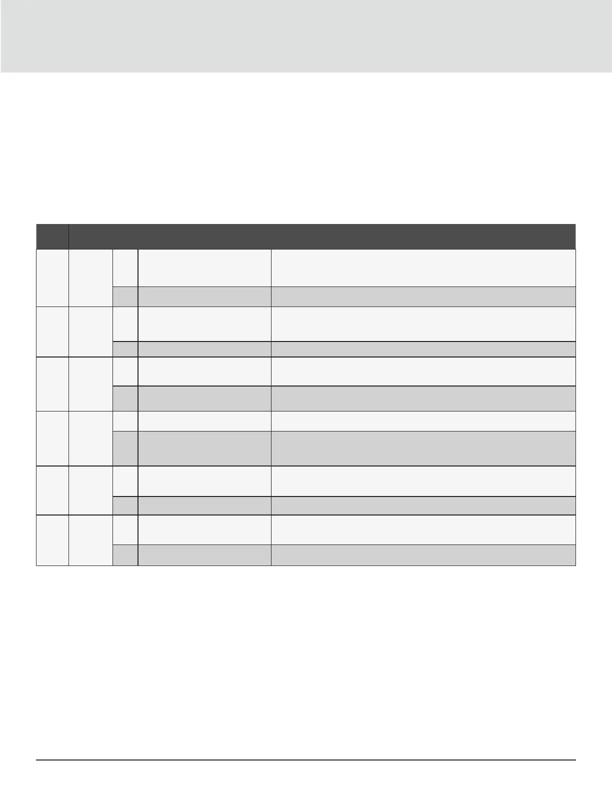
Table 2-4 Dry-contact Connection and Pin-out Descriptions
PORT
NO.
PORT
NAME
PIN
NO.
PIN NAME DESCRIPTION
1 Input 1
1
Disable/Battery mode shutdown/
Any mode shutdown (Remote
Comms Shutdown)
Default: Disable, can be set via the LCD settings page. User can choose dry contact
as NO/NC. when NO, Pin 1 and Pin 2 are shorted, the function is active. when NC, Pin
1 and Pin 2 are open, the function is active.
2 Signal Ground Signal Ground
2 Input 2
3
Disable/Battery mode shutdown/
Any mode shutdown (Remote
Comms Shutdown)
Default: Disable, can be set via the LCD settings page. User can choose dry contact
as NO/NC. when NO, Pin 1 and Pin 2 are shorted, the function is active. when NC, Pin
1 and Pin 2 are open, the function is active.
4 Signal Ground Signal Ground
3
555
Battery
Detection
5 EBC Detection (DSCHG)
Default: No EBC User can know the quantity of EBC, when NO, Pin 5 and Pin 6 link to
the defective port of EBC .
6 EBC Detection (THR)
Default: No EBC User can know the quantity of EBC, when NO, Pin 5 and Pin 6 link to
the defective port of EBC .
REPO
REPO
Input
7 +5V REPO power supply, 5-Vdc 100-mA
8 REPO Coil -NC
NC, activated when Pin 7 and Pin 8 is open
NOTE: For details on REPO connection and operation, see Connecting a Remote
Emergency Power-o (REPO) Switch below.
5 Output 5
9
Low Battery/On battery/ On
bypass/UPS fault
Default: Low battery, can be set via the LCD settings page. When the system has a
fault, short Pin 9 and Pin 10
10 Signal Ground Signal Ground
6 Output 6
11
Low Battery/On battery/ On
bypass/UPS fault
Default: UPS fault, can be set via the LCD settings page. When the system has a fault,
short Pin 11 and Pin 12
12 Signal Ground Signal Ground
 Loading...