Vertiv | Liebert® GXT5™ | Installer/User Guide 49
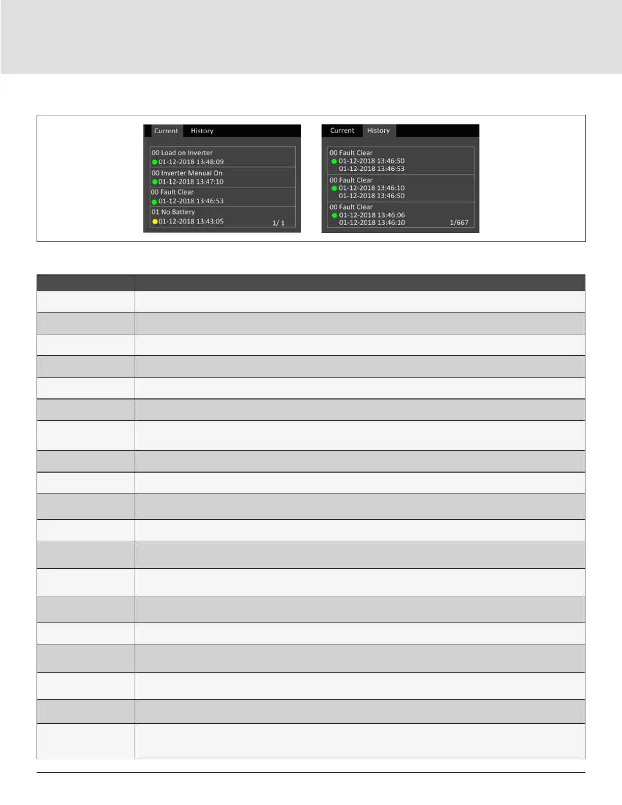
Figure 4-7 Current and History Log Tabs
Table 4-4 Alarm Messages
MESSAGE DESCRIPTION
Communication fail Internal communication is abnormal, please check the communication cables are connected correctly or not
Rectier fault The rectier is faulty and o
DC/DC fault The discharger is faulty, because the bus voltage exceeds the setting range when discharger starts or soft starts
DC bus abnormal The inverter is o when DC bus voltage is faulty. The load will transfer to bypass if the bypass is available
Charger fault The charger output voltage is abnormal, and the charger is o
Aux. power fault The auxiliary power output voltage exceeds the normal range
Inverter fault
The inverter is o when the inverter output voltage and current exceed the setting range. If bypass is available, the UPS will
transfer to bypass mode, otherwise the system will power o
Output short Check that the output cables are not shorted
Bypass backfeed Battery mode. The bypass relay is shorted or the SCR is damaged
Output o, voltage is not
zero
When there is no output, the system detects that the output has a voltage
Inverter relay welded The inverter relay is shorted
Parallel No. abnormal
The parallel online number is dierent from the setting number. Please check that the parallel number at ‘Settings’ page is
the same as the actual online number, and that the parallel cables are normal
Parallel comm fault
The local UPS and its online frequency conguration is dierent or the parallel address is conicted. Please check that the
parallel system parameter setting is the same as the local parameter setting
Parallel cable connection
abnormal
Detect the parallel cables are loosened
Input neutral lost The AC input mains N line is not detected. Please check that the input N line is opened or loosened
Input abnormal
The rectier and charger are o due to the mains voltage and frequency exceeding normal range. Check that the rectier
input phase voltage and frequency exceed the normal range or that the mains has power-o
Rectier overload
The output power is larger than the rectier overload point. Check that the input voltage meets the output load, mains
input 176 V ~ 100 V, the load 100% ~ 50% linear derating
Battery reversed The battery positive and negative are reversed. Please reconnect the battery and check the battery cables connection
Battery low pre-warning
This alarm occurs when the battery reaches the EOD. After the pre-warning, the battery capacity allows two minutes
discharge at full load. The user can set the time ranging from 2 min ~ 30 min, (2 min by default). Please shut down the load
timely
 Loading...