Installation drawings
C --- 7
Liebert HPM --- A/W/F/D/H
English
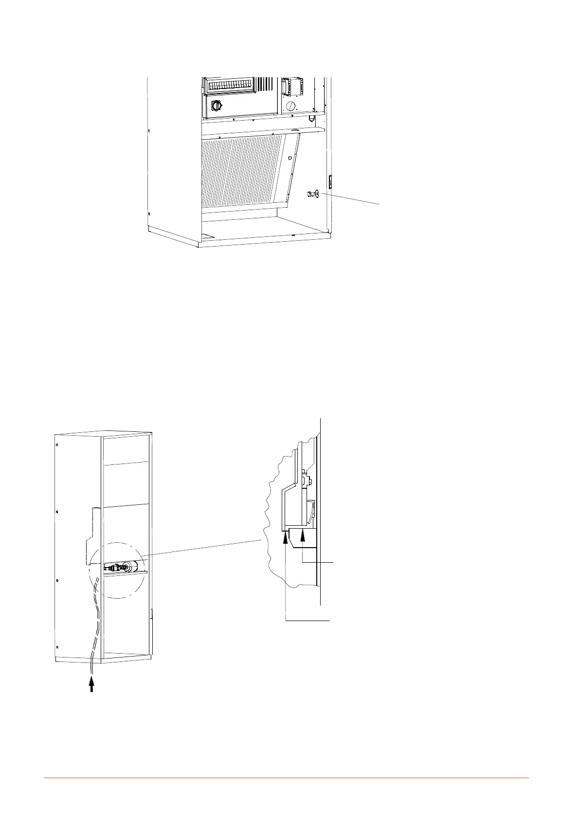
Fig. 14 --- Bleed valve position
Bleed valve position
S 1 G --- 2 E --- 2 G F / D / H
M2H...5D F/D/H models
Fig. 15 --- Supply cable path
Liebert HPM S0F...2G
Electrical connection path
through service area
UNDER/DISPLACEMENT
Electrical connection path
directly to the electrical
panel OVER