Refrigerant a
nd hydraulic connections
D---7 Liebert HPM --- A/W/F/D/H
English
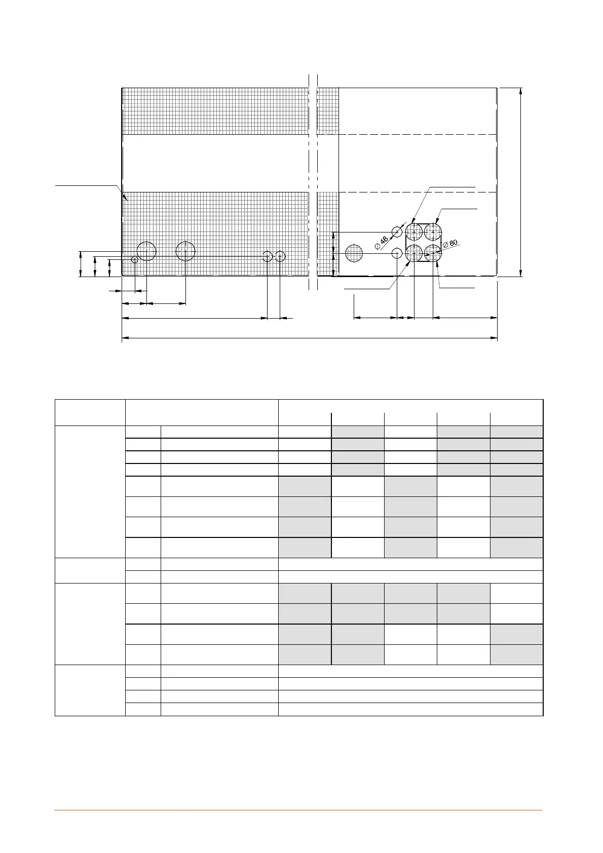
Fig. 7 --- Refrigerant, water and electrical connections Liebert HPM L8F --- 9H
UNIT FRONT
IFC
OFC
HD/HF
IHW
OHW
IWC1/IL1
IWC2/IL2
OWC2/OG2
OWC1/OG1
EC
CD
115 185
685 60
119
94
3038980
2550
890
203
80
60
109 101
Wire mesh
safety
screen (*)
(*) This must be cut in order to allow access for the pipes and cables
Models
Unit Con nection
Version
A W D H F
L 8 F --- 9 H
IL1
Refrigerant liquid line inlet 1 * OD 18 mm OD 18 mm
IL2
Refrigerant liquid line inlet 2 * OD 18 mm OD 18 mm
OG1
Refrigerant gas line outlet 1 * OD 22 mm OD 22 mm
OG2
Refrigerant gas line outlet 2 * OD 22 mm OD 22 mm
IWC1
Water to condenser 1 inlet
ISO 7/1
Rp 1¼ Rp 1¼
IWC2
Water to condenser 2 inlet
ISO 7/1
Rp 1¼ Rp 1¼
OWC1
Water from condenser 1 outlet
ISO 7/1
Rp 1¼ Rp 1¼
OWC2
Water from condenser 2 outlet
ISO 7/1
Rp 1¼ Rp 1¼
Lxx
IHW
Hotwaterinlet(opt.) OD 22 mm
OHW
Hot water outlet (opt.) OD 22 mm
L8F
IFC (F)
Water inlet to Freecooling
ISO 7/1
R2½
OFC (F)
Water outlet from Freecooling
ISO 7/1
R2½
IFC
(D+H)
W ater inlet to Dualfluid
ISO 7/1
R2½ R2½
OFC
(D+H)
Water outlet from Dualfluid
ISO 7/1
R2½ R2½
Lxx
CD
Condensate drain ID 20 mm
HF
Humidifier feed (opt.) --- ISO 7/1 R½
HD
Humidifier drain (opt.) ID 22 mm
EC
Electrical power supply
Hole 80 mm
* Connection size only. The dimension of the connecting pipe depends on unit model and refrigerant, see Tab. c on para. 4.1.2.