Liebert PCW - UM - 273895 - 04.10.2018 F - 1
Enclosure F - Infrared Humidier
F.1 - Infrared Humidier
The infrared humidier design consists of quartz lamps mounted above a stainless steel water reservoir. The lamps never come in contact
with the water. When humidication of room air is required, infrared rays generate water vapor-without impurities or odor, within seconds.
In order to obtain optimum performance from the humidier it is advisable to read this manual carefully.
Tab. 1 - Infrared Humidier specications
F.2 - Installation
The infrared humidier is supplied already mounted within the air conditioner. The only necessary operations are the connections for the
supply water and drain water.
Supply Water.
• Maximum water pressure 1000 kPa
• Size humidier supply line for 3.8 l/min, with a minimum water pressure of 138 kPa
• Do not supply de-ionized water to the humidier
Drain Water.
• This contains the same substances dissolved in the supply water, however in larger quantities;
• It may reach a temperature of 100 ° C;
• It is not toxic and can be drained into the sewerage system, category 3, EN 1717.
• Dispose the drain hose into an ordinary drainage network. The drainage network should have a siphon and must be able to withstand
temperatures up to 100° C
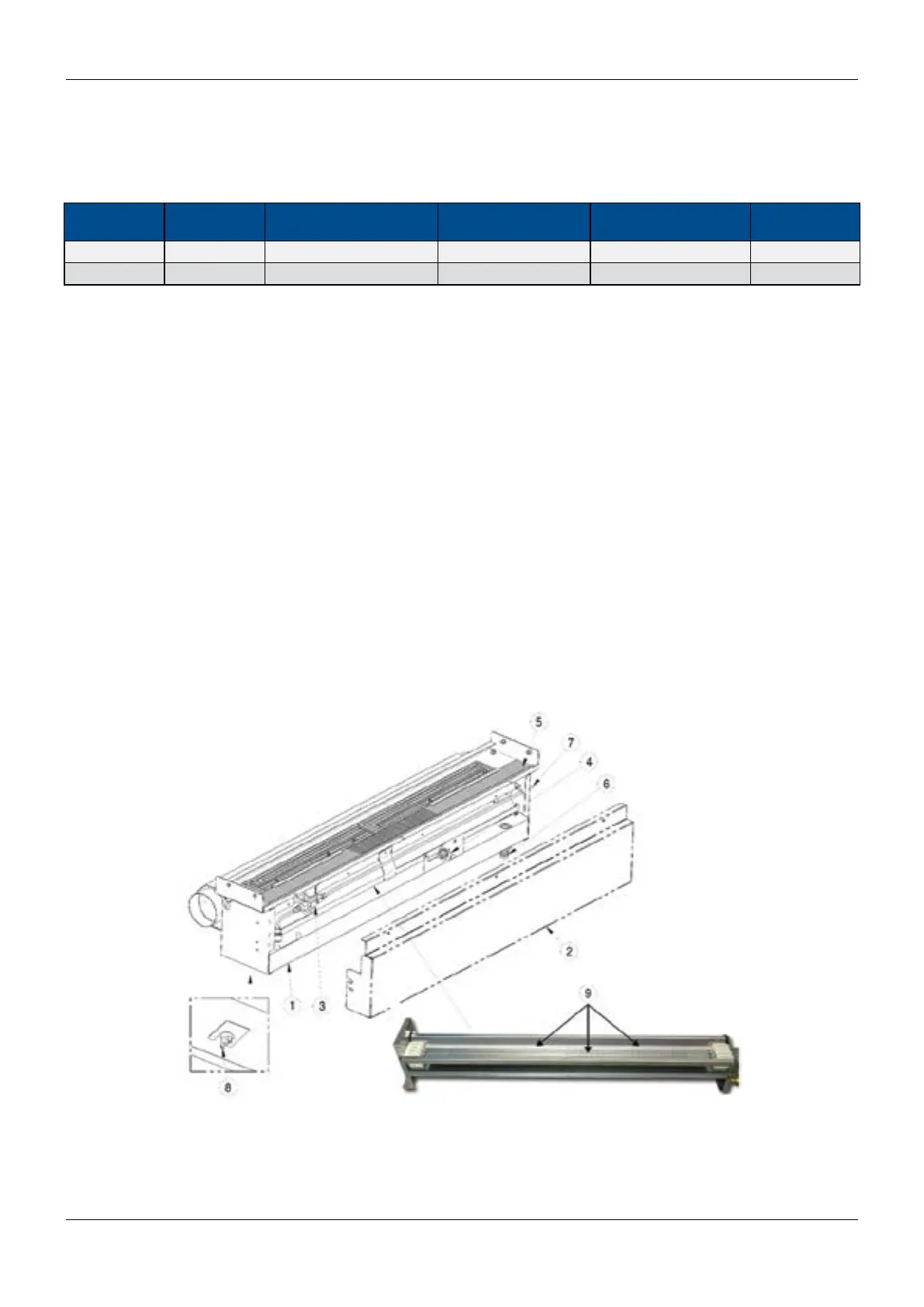
F.2.1 - Infrared humidier components
UNIT MODEL PAN
MAIN POWER SUPPLIES
(V ± 10%)
NOMINAL CAPACITY
[kg/h]
ABSORBED CURRENT
[A]
POWER INPUT
[kW]
PH025...040 Stainless steel 400V / 3ph / 50Hz 5 6.4 4.8
PH045...201 Stainless steel 400V / 3ph / 50Hz 10 13.9 9.6
1 humidier pan
2 cover
3 solenoid valve ow regulation
4 oat switch
5 humidier air lter
6 discharge connection
7 supply line
8 manual reset thermostat
9 infrared bulbs
Fig. 1 - The infrared humidier and its components