58
Transfer From Normal Mode To Maintenance Bypass Mode
When the UPS is running in Normal mode, you can use this procedure to transfer the load from inverter output to
maintenance bypass.
1.
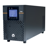
Remove the maintenance bypass switch baffle retaining screws, rotate the baffle upwards until it is locked in
position, and then fasten the retaining screws. As shown in Figure 5-13.
Figure 5-13 Moving the baffle upwards
At this point, the system Interlock function has been activated and the UPS will transfer to internal bypass mode;
you should confirm that the UPS has been transferred to internal bypass mode.
2.
After confirming, close the maintenance bypass switch Q3.
3.
Disconnect the output switch Q4.
4.
Unplugging the REPO terminal deactivates the rectifier, inverter, static switch and battery, but does not affect the
maintenance bypass power supply to the load.
5.
Disconnect the rectifier input switch Q1 and bypass input switch Q2. At this point, all the internal power supplies
are deactivated and the LCD screen is switched off.
6.
If the UPS is equipped with internal batteries, make sure that that they have been isolated from the UPS before
carrying out maintenance work on it. Refer to 6.10 for details.
Transfer From Maintenance Bypass Mode To Normal Mode
Following UPS maintenance operations, the following procedures may be used to transfer the load from the
maintenance bypass to the inverter.
1.
If the UPS is equipped with internal batteries, simply connect the UPS and internal batteries when you finish
servicing the UPS. Refer to 6.10 for details.
2.
Close the output switch Q4.
3.
Close the bypass input switch Q2.
4.
Following the LCD start-up, ensure that the system is operating in Bypass mode.