020573.02 13
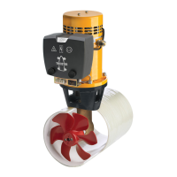
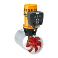
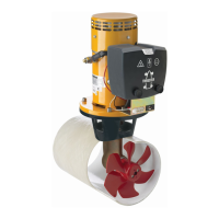
vetus® Operation manual and installation instructions bow thrusters BOW4512D
M8
12 - 15 Nm
6
Molykote® G-n plus
Outboard Gear
Grease
(9 - 11 ft.lbf )
M6
2 Nm
10
Outboard Gear
Grease
(1.5 ft.lbf)
The propeller should run a minimum of 1.5 mm (
1
/
16
”) free of the
thrust tube wall, all round.
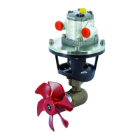
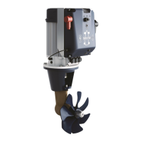
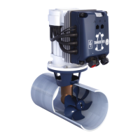
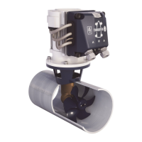
4.3 Final assembly
• Grease the propeller shaft with ‘outboard gear grease’ and install
the propeller.
• Slide the exible coupling onto the output spindle of the electric
motor as far as necessary to allow the end of the output spindle
(A) and the underside of the ange (B) to become aligned.
• Tighten the lock-screw (C).
• Grease the input shaft with an installation compound, like ‘Mo-
lykote® G-n plus’.
• Grease the threads of the fastenings bolts with ‘outboard gear
grease’ and install the electric motor to the intermediate ange.
• For a rst check, turn the propeller by hand, it should turn easily,
whilst being connected to the output spindle of the electric mo-
tor.
M5
3 Nm
2.5
(2.2 ft.lbf )
ENGLISH
 Loading...