14 020573.02
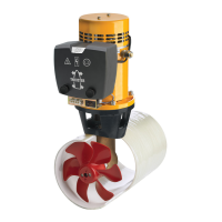
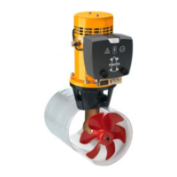
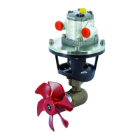
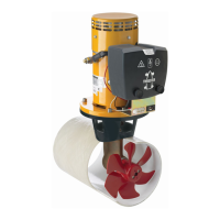
vetus® Operation manual and installation instructions bow thrusters BOW4512D
5 Electrical installation
Consult the chapter ‘Electrical Management’ in ‘Installation recom-
mendations for bow thrusters’, Vetus art. code 020571.03.
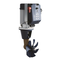
• Connect the main power supply cables.
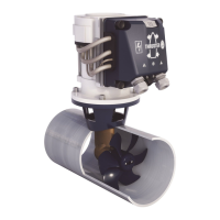
• Fit the control panel next to the steering position. There must be
at least 50 mm (2”) space behind the panel.
If 2 bow thrusters have to be operated simultaneously, for exam-
ple on a catamaran, consult the diagram on page 68.
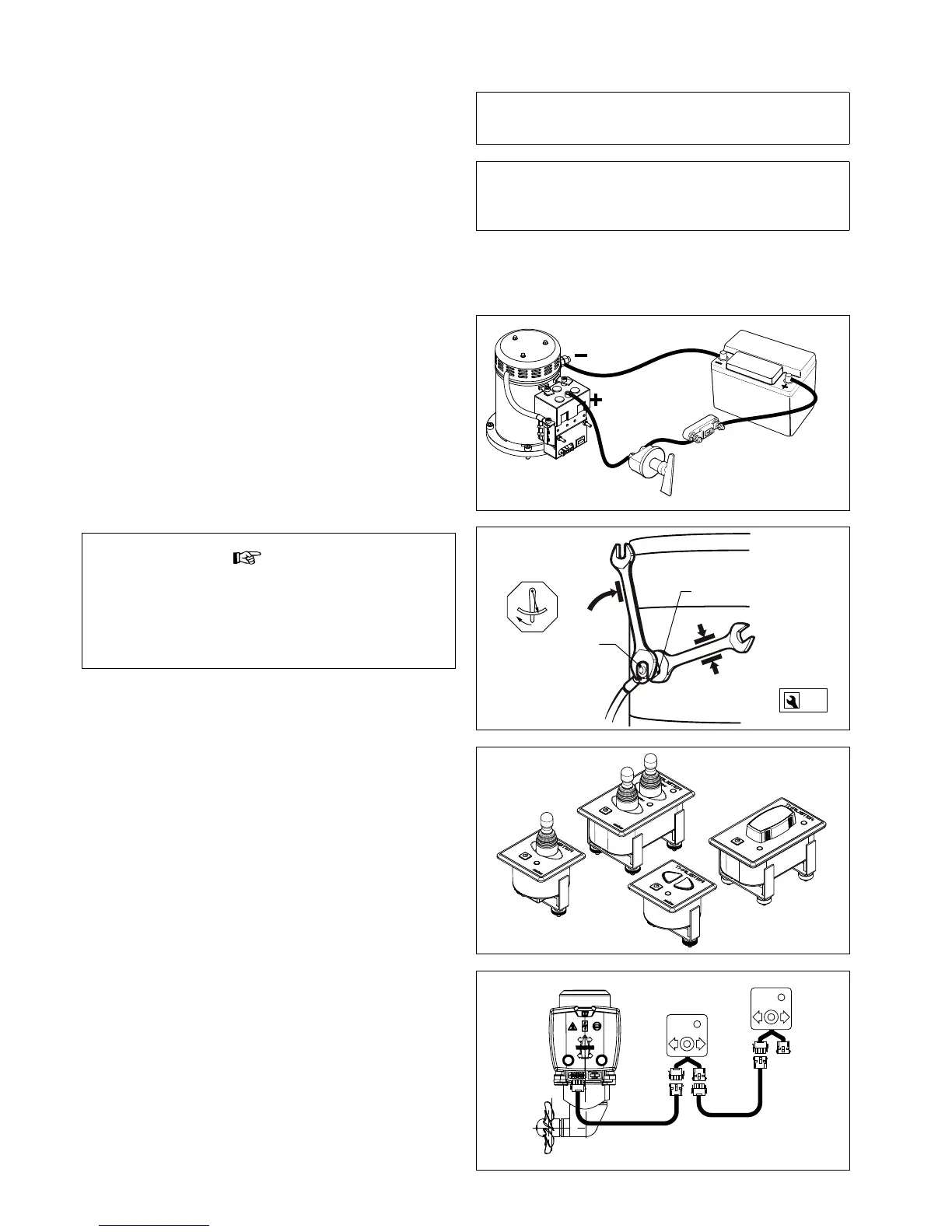
• Fit the control cable between the bow thruster and the control
panel through the vessel and connect the jack connections to-
gether.
If it is necessary to cut the intermediate cable and reconnect it
take care to ensure the correct colours are connected together.
N.B: The colours of the wire cores in the intermediate cable may
dier from the wire core colours as used on the bow thruster mo-
tor and on the control panel!
If there are two steering positions, the second control panel can
be connected to the rst one.
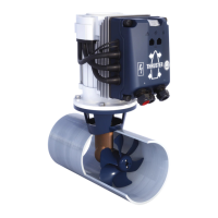
9 - 11 Nm
17
1
2
2 x M10
(6.5 - 8 ft.lbf )
Be careful not to rotate the bolt and nut 1 while connecting the
cables.
To prevent this happening, keep an open-ended spanner on nut
1 while screwing on bolt 2, without rotating this spanner.
The torque for nut 2 is a 9 - 11 Nm (6.5 - 8 ft.lbf).
Make sure that no other electrical parts come loose when con-
necting the electric cables.
Check all electrical connections after 14 days. Electrical parts
(such as bolts and nuts) may come loose as a result of uctua-
tions in temperature.
Check that the voltage, recorded on the motor type plate, is in agree-
ment with the vessel’s circuit voltage. Position the battery or batter-
ies as close as possible to the bow thruster; the main power supply
cables can then be short, which reduces the voltage drop as much
as possible.
See page 69 for the applicable battery capacity, the size of main pow-
er supply cables and fuse to use.
 Loading...