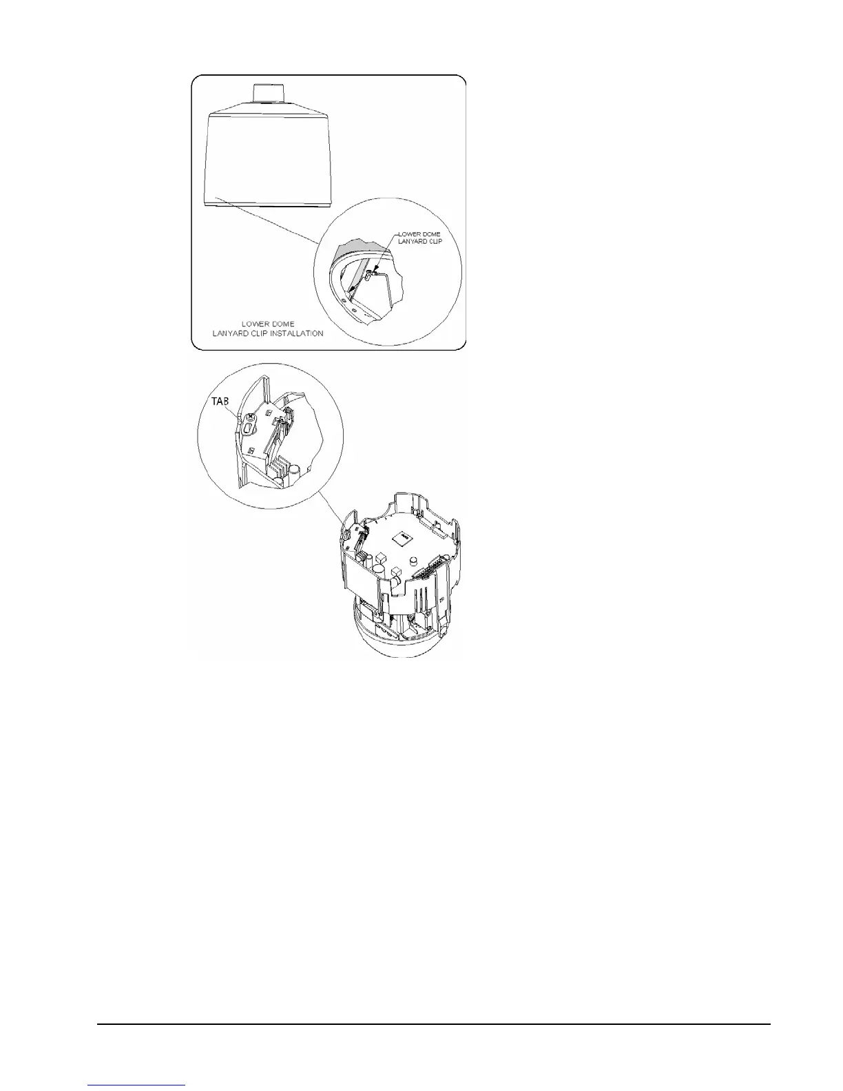
Figure 17
Installing the Safety Cords
14. Push the camera drive
straight up into the housing
until it snaps into the
housing. Do not use
excessive force. In the event
that it does not snap easily,
remove the SurveyorVFT
and verify proper cabling.
15. Holding the lower dome, line
up the 2 molded tabs on the
lower dome with the 2
parallel surfaces of the
housing. Push the lower
dome up and verify that it
snaps into place on both
sides. See Figure 18.
16. Tighten the 4 trim ring
captive screws to hold the
lower dome in place. Verify
proper orientation of the
grommet.
17. Proceed to the Operation
section of this manual.
XX134-01-00 Rev 205 SurveyorVFT Camera Dome System Installation • 23
 Loading...