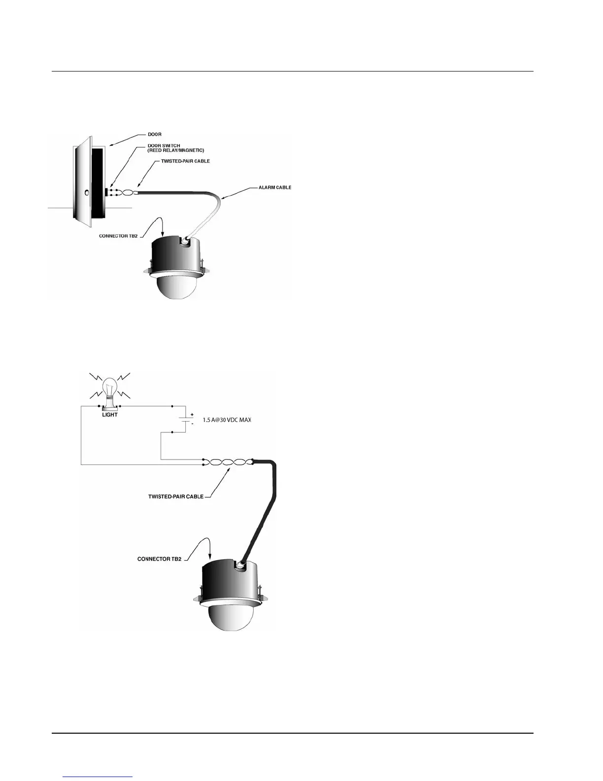
Typical Relay and Alarm Connections
Alarm input and relay output type signals are also carried on individually-shielded twisted-pair cable sets. The
signals are defined in the following descriptions.
Alarms 1-4 are electronic CMOS level type inputs that are driven by a dry contact type switch. These signals
are connected to terminal block TB2. Each input has
two states, open and closed. For example, in Figure
20, a door switch can activate an alarm when
connected to a SurveyorVFT alarm input. As a
guideline (under normal conditions), the cable should
be 22 AWG for a 1000 foot (305 m) distance. The
states correspond to defined TTL designations as
follows:
Figure 20
Typical Alarm Circuit
OPEN = HIGH and CLOSED = LOW
where: HIGH = 5 VDC and LOW = < 1 VDC
Since dry contact switches are normally defined in
terms of their inactive or “normal” state, the following
holds true:
NORMALLY CLOSED (NC) = ACTIVE HIGH
(OPEN)
NORMALLY OPEN (NO) = ACTIVE LOW (CLOSED)
The “active” state can be programmed through the SurveyorVFT menu system. These signals are
connected to terminal block TB2. Alarm signals
can be programmed for their status
(enabled/disabled), active level definition
(high/low), action/reset function (none, preset, aux
on, aux off or tour), acknowledgment mode
(automatic, momentary or manual) and report
status (yes/no).
Figure 21
Typical Relay Circuit
The relay output is an actual relay output dry
contact, which directly drives external devices (1.5
A @30 VDC max). For example, a light can be
turned on and off when the relay output is
connected to the light circuit. Refer to Figure 21.
The relay output contact can be programmed for
its power-on state definition (on/off) and output
type definition (momentary or latching).
There is one relay output dry contact located on
terminal block TB3. Connect the circuit to be
switched to the connector pins labeled RELAY C
(relay common) and RELAY NC or RELAY NO for
a normally closed or normally open connection,
respectively.
28 • Wiring XX134-01-00 Rev 205 SurveyorVFT Camera Dome System