Outdoor Pendant Model
The Outdoor Pendant model mounts on a Vicon mount (refer to the table in the Introduction section) or a 1.5-
inch vertical pipe with appropriate coupling in the same manner as the indoor version. The outdoor version
includes a sunshield, heater and weather protection.
Outdoor Pendant Overview
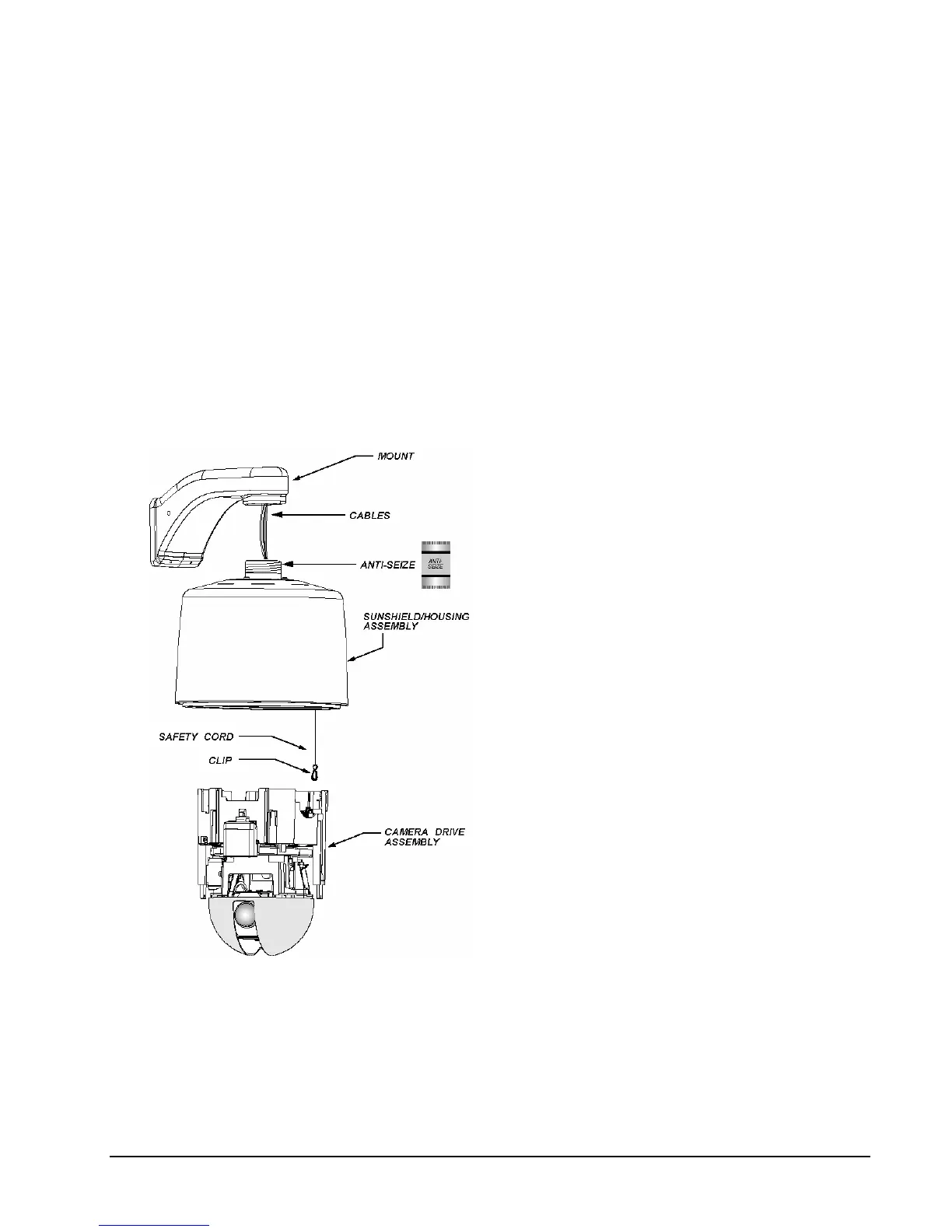
The mount is installed with all the cables run through it or the 1.5-inch NPT pipe is prepared with lubricant for
the housing and the SurveyorVFT installation. The cables are routed through the housing and the housing is
screwed tightly to the pipe. Then the customer interface board is wired. The SurveyorVFT is hung from the
housing safety cord. The SurveyorVFT drive is then carefully snapped into the housing. The entire
SurveyorVFT is supported by the mount. The outdoor lower dome is then snapped on and screwed tight to
the SurveyorVFT. See Figure 15. Detailed installation instructions will follow.
The accessory kit contains the removable terminal blocks to be used for connections in this installation. The
mount must provide a support of suitable strength for the outdoor pendant SurveyorVFT weight of 7.7 lb
(3.5 kg).
1. Install the mount in accordance with the
installation manual included with the mount or
prepare the vertical 1.5-inch NPT pipe.
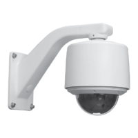
Figure 15
Outdoor Pendant Mount Model
2. Feed all necessary cables through the back of
the mount or out the end of the 1.5-inch NPT
pipe.
3. Unlatch and rotate the customer interface
board 90º downward to provide access to the
terminal blocks. (The board can be completely
removed if necessary by snapping it out of the
hinge after rotated to the 90º downward
position.)
4. Apply the provided anti-seize lubricant to the
first 2-3 unpainted threads of the housing.
5. Lift the sunshield/housing up to the mount and
feed the cables through its top opening.
6. Place the housing onto the 1.5-inch pipe and
screw clockwise, looking up at the housing.
When it becomes snug, turn it an additional
quarter-turn.
7. Remove terminal blocks from the accessory
kit. The 2-pin is for power, the two (2) 8-pin are
for alarms and control/relay; the 3-pin is for
UTP option. Terminate all the cables as
follows:
XX134-01-00 Rev 205 SurveyorVFT Camera Dome System Installation • 21
 Loading...