Operation
Following the complete installation and setup of the SurveyorVFT, it is necessary to perform initial power-up
testing and verify proper operation. If the SurveyorVFT fails to power-up correctly, go to the Troubleshooting
sub-section of this section. When initial power-up has been completed and verified, SurveyorVFT can be
setup and operated in a normal fashion using a Vicon remote operator keypad, VPS/NOVA unit or through a
PC running the Surveyor Direct Control program; the ViconNet can be run from a ViconNet workstation.
Initial Power-Up
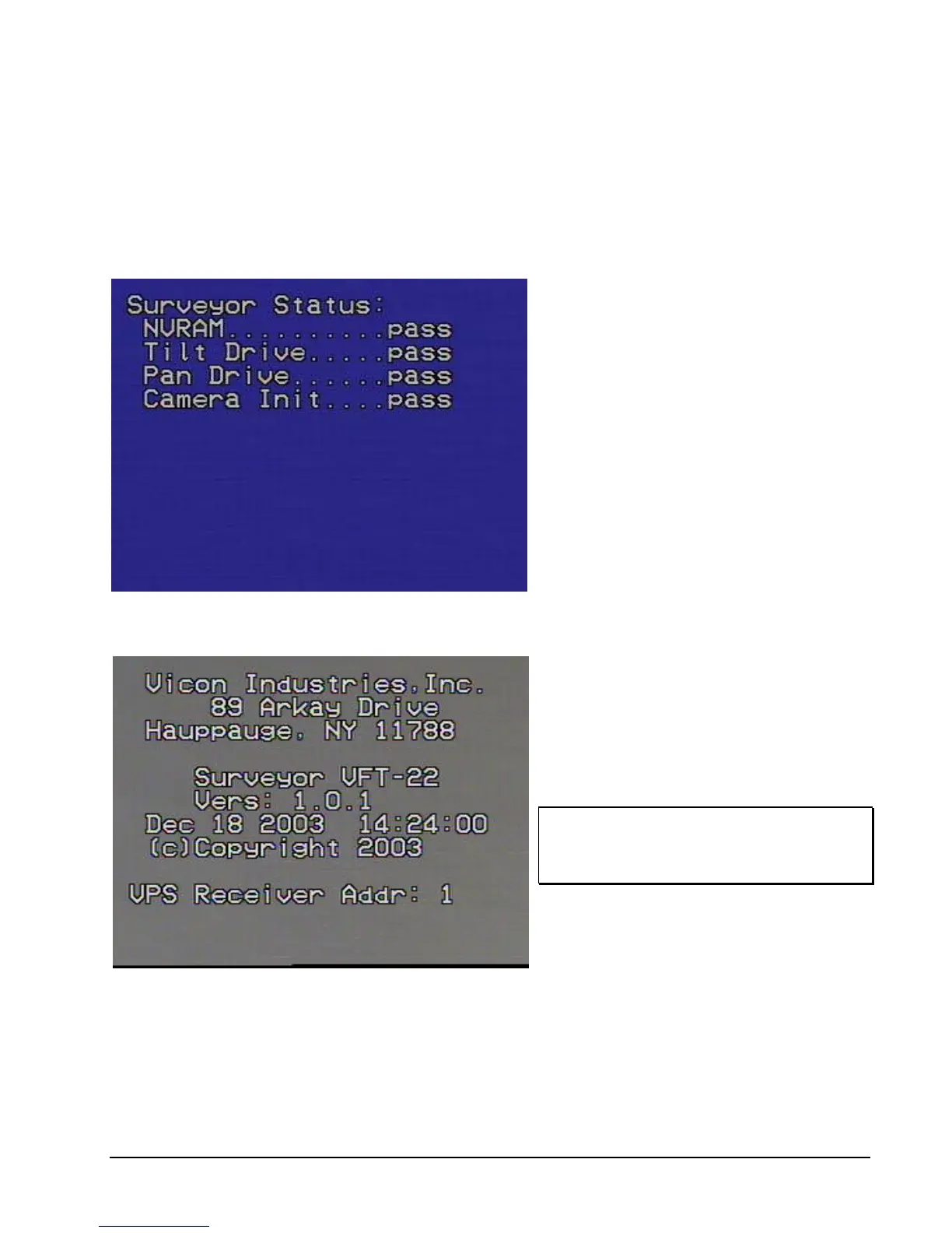
Figure 26
Power-Up Test Screen
1. Setup an appropriate monitor within the
vicinity of the SurveyorVFT. Connect the
video out cable to the monitor. Power-on
the monitor and verify that no signal is
displayed.
2. Verify that the SurveyorVFT has been
installed, wired and configured in
accordance with this manual.
3. Switch the AC power on to the
SurveyorVFT. The monitor will display the
power-up test screen (Figure 26) for the
duration of its initial testing. This test
displays the status of the functions pan, tilt,
zoom, focus and the integrity of the
memory (NVRAM). If any test fails, “FAIL”
displays in place of “PASS.”
4. The SurveyorVFT then switches to the
opening screen (Figure 27). This screen
will display the camera dome program
version, current date/time and some of the
current DIP switch settings. Upon
completion of homing, the SurveyorVFT is
ready to verify proper operation. (Note:
Figure 27 is only a sample screen.)
Figure 27
Opening Screen
NOTE: The camera drive always returns to the
pan and tilt coordinates it was initially
powered-up with unless autohome on
power-up was set.
XX134-01-00 Rev 205 SurveyorVFT Camera Dome System Operation • 47