Configuration
The SurveyorVFT must be configured for its address and mode and termination setting when using RS-
422/RS-485 protocol. The address and mode are set using the two 8-position DIP Switch banks SW1 and
SW2. It is necessary to determine which communication mode, Camera/Lens Module type and SurveyorVFT
address is required prior to configuration. Configuration should be performed just prior to final assembly and
installation. The termination setting is configured using 3 jumpers. This termination setting does not apply to
RS-422 mode.
Setting the DIP Switches
This section defines how to set DIP switches 1 and 2 (SW1 and SW2) on the Main Board.
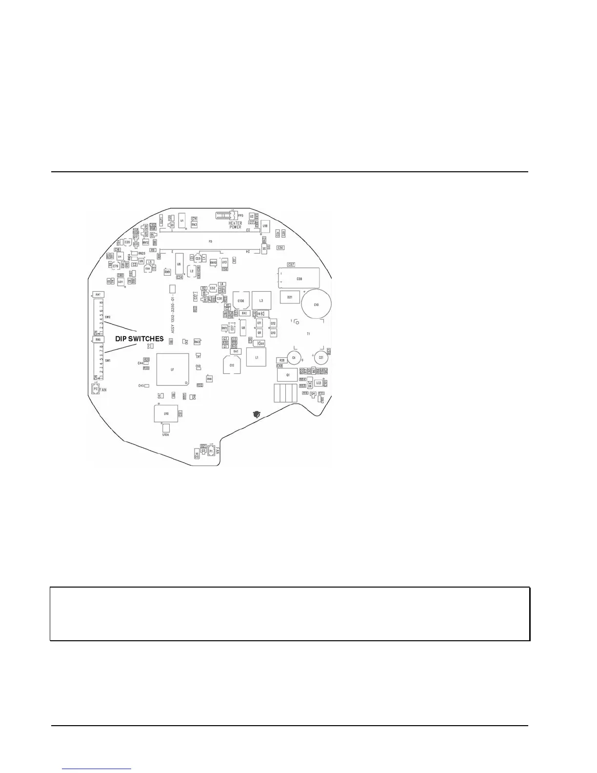
Figure 22
DIP Switch Location
Refer to Figure 22 for DIP switch
location and Figure 23 for DIP switch
label. DIP switch 1 (SW1) is used to
set the address as explained later. DIP
switch 2 (SW2) is used to set the
mode functions and protocol. Position
1 is the video mode setting, NTSC
(ON) or PAL (OFF). Position 2 is the
communication mode setting, Vicoax
mode (ON) or Serial (OFF). Serial
selection enables twisted pair
compatibility to other manufacturer’s
protocol. Position 3 is the
communication type setting, SIMPLEX
(ON) or HALF DUPLEX (OFF).
Position 4 is the protocol mode setting,
RS-485 (ON) or RS-422 (OFF).
Switches 5-8 select other
manufacturer’s protocols. Each switch
is numbered from 1 to 8 and marked
to indicate the ON position.
SurveyorVFT will automatically detect
the system’s baud rate and supports
4800, 9600 and 19,200 kb/sec rates.
For RS-422/485 Mode:
1. Set switches 1 - 8 on DIP switch 1 (SW1) to SurveyorVFT’s address as specified in Table 3. All
addresses between 0 and 255 are valid (address 0 is the same as camera number 256). See Figure 23.
2. Set switch 1 on DIP switch 2 (SW2) to the appropriate video mode (PAL/OFF or NTSC/ON).
3. Set switch 2 on DIP switch 2 (SW2) to the OFF position (SERIAL).
4. Set switch 3 on DIP switch 2 (SW2) to the appropriate communication mode (SIMPLEX or DUPLEX).
5. Set switch 4 on DIP switch 2 (SW2) to the appropriate communication protocol (RS-422 or RS-485).
6. Set switches 5-8 on DIP switch 2 (SW2) to the appropriate manufacturer protocol. See Figure 23.
NOTE: Switch 4 must be set to RS-485 protocol to enable daisy chain operation; switch 4 must be set to
RS-422 protocol to enable star operation.
NOTE: All SurveyorVFTs in a daisy chain or star configuration must have unique addresses for proper
operation.
For Vicoax Mode:
1. Set switch 1 on DIP switch 2 (SW2) to the appropriate video mode (PAL or NTSC).
2. Set switch 2 on DIP switch 2 (SW2) to the ON position (Vicoax mode).
3. Set switches 3 and 4 on DIP switch 2 (SW2) to either position, as it does not affect Vicoax protocol
operation.
38 • Configuration XX134-01-00 Rev 205 SurveyorVFT Camera Dome System