Introduction
The information in this manual covers the installation, configuration and operation of the SurveyorVFT
Camera Dome. This system should only be installed by a qualified technician using common hand tools and
approved materials and wiring methods in accordance with the national Electric Code ANSI/NFPA 70, state
and local wiring codes.
NOTE: Read all instructions before beginning any installation.
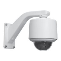
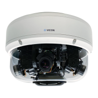
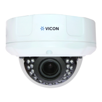
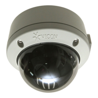
The SurveyorVFT is a compact, lightweight intelligent security device comprised of a camera, pan/tilt drive,
receiver and CPU-based electronics all in an attractive and covert enclosure. SurveyorVFT can be
programmed and operated using any V1300X/V1400X/1500 series of NOVA communication devices and
enhanced Vicoax II protocol. SurveyorVFT is sold in a variety of prepackaged configurations with choices in
environment, mounting configuration, camera type, and lower dome types. Refer to Table 1 for a complete list
of model numbers. Refer to product specification V134-0X and V134-2X (ViconNet version) for a list of
optional equipment, including power supplies, mounts, lower domes and receivers.
The basic SurveyorVFT provides video transmission over coaxial cable. Options are available that provide
TCP/IP (ViconNet), fiber-optic and twisted-pair (UTP/NVT) video transmission. Each of these options includes
an interface board that allows the specific type of video transmission. An appropriate receiver is required for
UTP/NVT and fiber optic versions. The ViconNet option provides support for direct network connection to
Kollector Elite Digital Video Recorders and ViconNet Workstations via ViconNet software. A pre-installed LAN
interface board allows direct plug-in to a system network hub, switch or router. Video from the camera is
available to all network recorders and workstations for live view and recording. The Vicon SurveyorVFT
camera dome can be used in conjunction with competitive PTZ drivers through DIP switch selection.
The SurveyorVFT is designed for easy snap-in installation. The drive simply snaps into the housing. When
removed, the housing retains all programmed functions in its on-board memory. The customer interface
board snaps down for easy access and the PCB provides removable terminal blocks for simple wiring
connections. Several mounting accessories are available to fit almost any installation need.
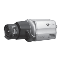
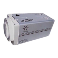
There are three camera types available, each with NTSC and PAL versions. The basic model is a 22X high-
resolution camera/lens. Another 22X model is available with ExVIew CCD technology (22XEX). The third
version is a 23X day/night camera/lens. See Technical Information for camera features.
Refer to tables below for specific model numbers and options available. Call your Vicon representative for
model availability. All versions use the same firmware for programming and operation. For programming,
refer to the SurveyorVFT Programming Manual XX134-4X.
SurveyorVFT meets requirements for an FCC Class A computing device. SurveyorVFT complies with the fire
code of certain local municipalities. The fire code for any given municipality should be verified for
SurveyorVFT’s compliance at the installation site.
Vicon strongly recommends the use of line conditioners, voltage regulators and uninterruptible power supply
(UPS) systems in the electrical power service. The electronic components within the SurveyorVFT are
sensitive to damage from ESD (Electro-Static Discharge). Appropriate precautions and proper use of a
ground strap should be observed at all times when handling the unit or its subassemblies.
XX134-01-00 Rev 205 SurveyorVFT Camera Dome System Introduction • 1