AIRSUPPLYREQUIREMENTS
The required air pressure for Series 769 FireLock NXT Preaction Valves
is 13 psi/0.9 Bar minimum, regardless of the system supply water pres-
sure. Normal air pressure should not exceed 18 psi/1.2 Bar. Failure to
maintain air pressure within the 13 psi/0.9 Bar to 18 psi/1.2 Bar range
may reduce system operation response time.
Systems with air pressure higher than 18 psi/1.2 Bar may require the
addition of a Series 746-LPA Dry Accelerator. NOTE: The Series 746-
LPA Dry Accelerator must be used only on systems operating below
25 psi/1.7 Bar of air. If air pressure higher than 25 psi/1.7 Bar is required,
the Series 746 Dry Accelerator should be used.
If multiple Series 769 FireLock NXT Preaction Valves are installed with
a common air supply, isolate the systems with a spring-loaded, soft-
seated ball check valve to ensure air integrity for each system. Good
practice is to include a ball valve for isolation and service of each
individual system. Multiple valves require shop air or a tank-mounted air
compressor.
Set the air pressure to the required system air pressure. Air pressure
differing from the required system air pressure could delay system
operation response time.
The engineer/system designer is responsible for sizing the compressor
so that the entire system is charged to the required air pressure within
30 minutes. DO NOT oversize the compressor to provide more airflow.
An oversized compressor will slow down or possibly prevent valve opera-
tion.
If the compressor fills the system too fast, it may be necessary to
restrict the air supply. Restricting the air supply will ensure that air
being exhausted from an open sprinkler or manual release valve is not
replaced by the air supply system as fast as it is being exhausted.
COMPRESSORSIZING
0
2
4
6
8
10
12
SYSTEM CAPACITY (in gallons)
REQUIRED FLOW RATE (CFM)
COMPRESSOR REQUIREMENTS
550
300
50
800
1050
1300
1550
1800
20 psi/138 kPa
13 psi/90 kPa
BASEORRISER-MOUNTEDAIRCOMPRESSORS
For base or riser-mounted air compressors, the recommended air
pressure of 13 psi/0.9 Bar is the “on” or “low” pressure setting for
the compressor. The “off” or “high” pressure setting should be
18 psi/1.2 Bar.
When a base or riser-mounted air compressor supplies air to a Series
769 FireLock NXT Preaction Valve, do not install the Victaulic Series
757 Regulated Air Maintenance Trim Assembly (AMTA). In this case,
the air line of the compressor connects to the valve trim at the air
manifold (refer to the applicable trim drawing). If the compressor is not
equipped with a pressure switch, the Series 757P Air Maintenance Trim
Assembly with Pressure Switch should be installed.
NOTICE
• TheSeries757PAMTAmustnotbeusedinanysystem
installedwithaSeries746-LPADryAccelerator,unlessatank
andanairregulatorareadded.
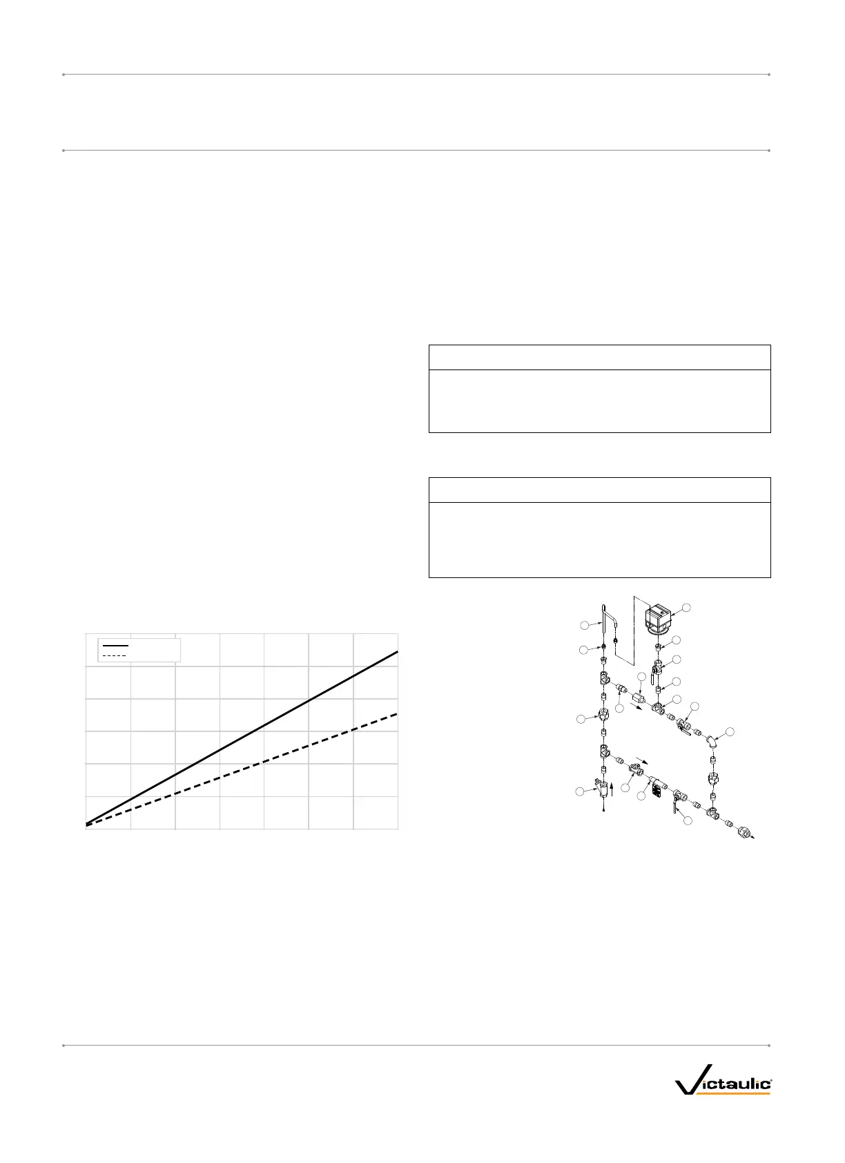
VICTAULICSERIES757PAIRMAINTENANCETRIMASSEMBLY
(AMTA)WITHPRESSURESWITCHOPTION
NOTICE
• RefertotheI-757PAirMaintenanceTrimAssemblywith
PressureSwitchInstallationInstructions,suppliedwiththe
product,forcompleteinstallation,electrical,andpressure
switchadjustmentinformation.
5
2
12
7
8
15
10
16
9
6
4
1
13
3
14
11
TO
SYSTEM
FROM
COMPRESSOR
Bill of Materials
Item Qty. Description
1 1 Restrictor (½-inch NPT)
2 1 Strainer (½-inch NPT)
3 1 Swing Check (½-inch NPT)
4 1 Slow-Fill Ball Valve
(Normally Open)
5 1 Spring-Loaded, Soft-Seated
Check Valve
6 1 Pressure Switch
7 2 Compression Fitting, Straight
(¼-inch NPT x ¼-inch Tube)
8 1 Copper Tubing (¼-inch OD)
9 11 Close Nipple
(½-inch NPT x 1.13)
10 1 Nipple (½-inch NPT x 4.00)
11 1 90° Female Elbow (½-inch NPT)
12 4 Female Tee (½-inch NPT)
13 3 Union (½-inch NPT)
14 2 Reducing Bushing
(½-inch NPT x ¼-inch NPT)
15 1 Fast-Fill Ball Valve
(Normally Closed)
16 1 Pressure Switch Isolation Ball
Valve (Normally Open -
Lockable)
I-769P.AC/ELEC_10
FireLockNXT™AutoConvertPreactionValve
SERIES 769
PreactionElectricAutoConvertDryTrim
I-769P.AC/ELEC
INSTALLATION,MAINTENANCE,ANDTESTINGMANUAL
www.victaulic.com
VICTAULIC IS A REGISTERED TRADEMARK OF VICTAULIC COMPANY. © 2009 VICTAULIC COMPANY. ALL RIGHTS RESERVED. PRINTED IN THE USA.
REV_B

 Loading...


