REMOVINGANDREPLACINGTHEDIAPHRAGMASSEMBLY
1. Remove the system from service by following steps 1 – 11 of the
“Required Internal Inspection” section.
2. Break the unions that connect the trim to the diaphragm cover.
Refer to the applicable trim drawing for details.
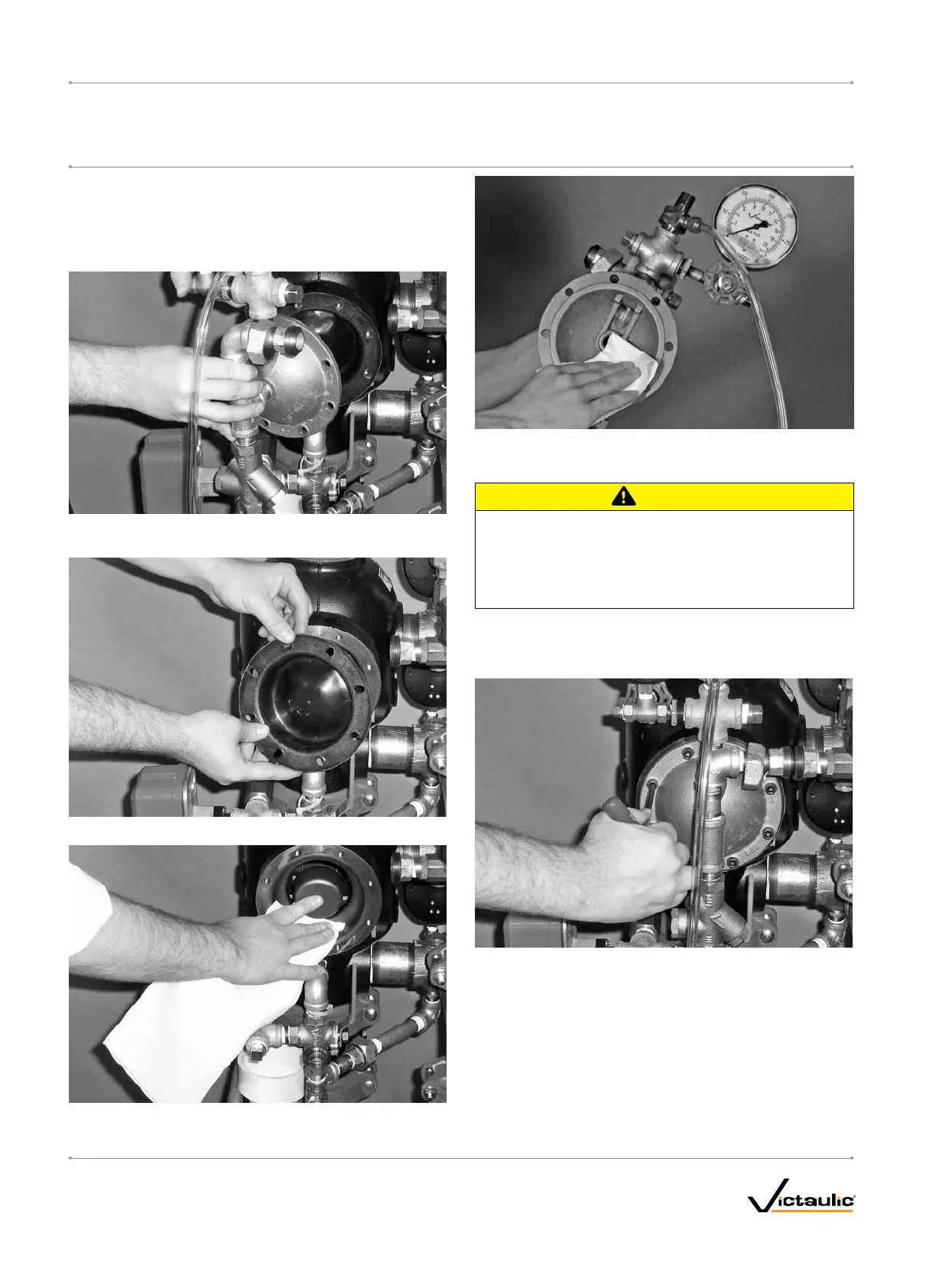
3. Remove the cap screws from the diaphragm cover, and pull the
diaphragm cover/trim off the valve.
4. Remove the diaphragm from the valve body.
5. Clean the back of the valve body to remove any debris that may
interfere with proper diaphragm seating.
5a. Clean the inside of the diaphragm cover to remove any foreign
material.
CAUTION
• Usecautionwheninstallinganewdiaphragmintothevalve
body.
Failuretofollowthisinstructioncouldcausedamagetothe
diaphragm,resultinginimpropervalveoperationandvalve
leakage.
6. Replace the diaphragm with a new, Victaulic-supplied diaphragm.
Align the holes in the diaphragm with the holes in the valve body.
Be careful not to damage the diaphragm during installation.
7. Align the holes of the diaphragm cover with the holes in the dia-
phragm/valve body. Tighten all cap screws into the diaphragm
cover/valve body.
8. Re-attach the trim at the unions that were loosened in step 2.
Refer to the applicable trim drawing for details. MAKESURE
ALLUNIONSTHATWERELOOSENEDTOPERMITACCESS
TOTHEDIAPHRAGMCOVERARERE-TIGHTENEDBEFORE
ATTEMPTINGTOPLACETHESYSTEMBACKINSERVICE.
9. Place the system back in service by following the “Placing the
System in Service” section.
I-769P.AC/ELEC_46
FireLockNXT™AutoConvertPreactionValve
SERIES 769
PreactionElectricAutoConvertDryTrim
I-769P.AC/ELECINSTALLATION,MAINTENANCE,ANDTESTINGMANUAL
www.victaulic.com
VICTAULIC IS A REGISTERED TRADEMARK OF VICTAULIC COMPANY. © 2009 VICTAULIC COMPANY. ALL RIGHTS RESERVED. PRINTED IN THE USA.
REV_B

 Loading...


