SAMPLEPROGRAMFORSYSTEMSENSOR
PDRP-2001PANEL
SYSTEMSETUP
5. Select 2=ZONE 2
1. Enter programming mode
6. Go to EDIT mode and set the following
2. Down arrow to 3= SYSTEM SETUP
1=ENABLED
3. Select 2=TIMERS
2=TYPE SUPERVSRY AR
4. Select 1=SOAK 1
3=OUTPUT CIRCUIT MAP
5. Select 1=ALWAYS ON
7. Press , 2=DESCRIPTION
6. Down arrow to screen 2 TIMERS
8. Type “CONVERT PRESSURE”
7. 1=AC LOSS DELAY, set to 0
9. Return to INPUT ZONES
8. Return to main menu PROGRAMMING
10. Select 3=ZONE 3
11. Go to EDIT mode and set the following
OUTPUTCIRCUITS
1=ENABLED
1. Select 3=OUTPUT CIRCUITS
2=TYPE WATERFLOW
2. Select 1=OUTPUT 1
3=OUTPUT CIRCUIT MAP
3. Set to the following
1=ALARM NAC YES
1=ENABLED YES
2=RELEASE 1 NO
2=TYPE ALARM NAC
12. Return to INPUT ZONES, press
4. Return to OUTPUT CIRCUITS
13. Select 1=ZONE 4
5. Select 2=OUTPUT 2
14. Go to EDIT mode and set the following
6. Set to the following
1=ENABLED
1=ENABLED YES
2=TYPE LOW PRESSURE AR
2=TYPE RELEASE CIR 1 UPSUPV SHORTS
3=OUTPUT CIRCUIT MAP
7. Return to OUTPUT CIRCUITS
15. Return to INPUT ZONES, press
8. Select 3=OUTPUT 3
16. Select 2=ZONE 5
9. Set to the following
17. Go to EDIT mode and set the following
1=ENABLED YES
1=ENABLED
2=TYPE SUPV BELL NAC
2=TYPE SUPERVSRY AR
10. Return to OUTPUT CIRCUITS, press
3=OUTPUT CIRCUIT MAP
11. Select 1=OUTPUT 4
18. Press , 2=DESCRIPTION
12. Set to the following
19. Type “WATER VALVE OFF”
1=ENABLED YES
20. Return to INPUT ZONES, press
2=TYPE TROUBLE BELL NAC
21. Select 3=ZONE 6
13. Return to main menu PROGRAMMING
22. Go to EDIT mode and set the following
1=ENABLED
INPUTZONES
2=TYPE SUPERVSRY AR
1. Select 2= INPUT ZONES
3=OUTPUT CIRCUIT MAP
2. Select 1=ZONE 1
23. Press , 2=DESCRIPTION
3. Go to EDIT mode and set the following
24. Type “CONVERT MODULE FAULT”
1=ENABLED
25. Press “ESC” several times to end
2=TYPE 2-WIRE SMOKE
3=OUTPUT CIRCUIT MAP
1=ALARM NAC YES
2=RELEASE 1 YES
4. Return to INPUT ZONES
I-769P.AC/ELEC_18
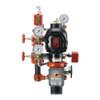
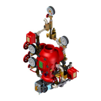
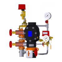
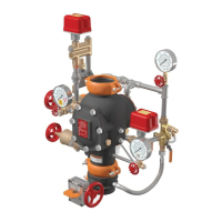
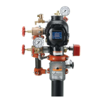
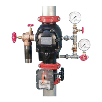
FireLockNXT™AutoConvertPreactionValve
SERIES 769
PreactionElectricAutoConvertDryTrim
I-769P.AC/ELEC
INSTALLATION,MAINTENANCE,ANDTESTINGMANUAL
www.victaulic.com
VICTAULIC IS A REGISTERED TRADEMARK OF VICTAULIC COMPANY. © 2009 VICTAULIC COMPANY. ALL RIGHTS RESERVED. PRINTED IN THE USA.
REV_B

 Loading...
