TABLEOFCONTENTS
Hazard Identification . . . . . . . . . . . . . . . . . . . . . . . . . . . . . . . . . . . . . . 1
Installer Safety Instructions . . . . . . . . . . . . . . . . . . . . . . . . . . . . . . . . . 2
General . . . . . . . . . . . . . . . . . . . . . . . . . . . . . . . . . . . . . . . . . . . . . . 2
Maintenance and Testing . . . . . . . . . . . . . . . . . . . . . . . . . . . . . . . . . 2
Introduction . . . . . . . . . . . . . . . . . . . . . . . . . . . . . . . . . . . . . . . . . . . . . 2
Trim Dimensions . . . . . . . . . . . . . . . . . . . . . . . . . . . . . . . . . . . . . . . . . 3
Exploded View Drawing – Trim Components . . . . . . . . . . . . . . . . . . . . 4
Exploded View Drawing – Internal Valve Components. . . . . . . . . . . . . . 6
Description - AutoConvert Trim Assembly . . . . . . . . . . . . . . . . . . . . . . 7
Latching Solenoid Module Cutaway . . . . . . . . . . . . . . . . . . . . . . . . . . . 7
Section View Drawing and Description –
Series 776 Low-Pressure Actuator . . . . . . . . . . . . . . . . . . . . . . . . . . 8
Section View Drawing and Description –
Series 746-LPA Dry Accelerator. . . . . . . . . . . . . . . . . . . . . . . . . . . . 9
Air Supply Requirements . . . . . . . . . . . . . . . . . . . . . . . . . . . . . . . . . . 10
Compressor Sizing . . . . . . . . . . . . . . . . . . . . . . . . . . . . . . . . . . . . . 10
Base or Riser-Mounted Air Compressors . . . . . . . . . . . . . . . . . . . . 10
Victaulic Series 757P Air Maintenance Trim Assembly
(AMTA) with Pressure Switch Option . . . . . . . . . . . . . . . . . . . . . 10
Shop Air or Tank-Mounted Air Compressors. . . . . . . . . . . . . . . . . . 11
Victaulic Series 757 Regulated Air Maintenance
Trim Assembly (AMTA) Option . . . . . . . . . . . . . . . . . . . . . . . . . . 11
Compressor Requirements and Settings for
Series 769 FireLock NXT Preaction Valves
Installed with Series 746-LPA Dry Accelerators . . . . . . . . . . . . . 11
Settings for Air Supervisory Pressure Switches
and Alarm Pressure Switches . . . . . . . . . . . . . . . . . . . . . . . . . . 11
Remote System Test Valve Requirements. . . . . . . . . . . . . . . . . . . . 11
Important Installation Information . . . . . . . . . . . . . . . . . . . . . . . . . . . 11
Valve/Trim Installation . . . . . . . . . . . . . . . . . . . . . . . . . . . . . . . . . . . . 12
Compression Fitting and Tube Installation . . . . . . . . . . . . . . . . . . . 12
Hydrostatic Testing . . . . . . . . . . . . . . . . . . . . . . . . . . . . . . . . . . . . . . 12
System Sensor PDRP-2001 Field Wiring Diagram (Standard) . . . . . . . 14
System Sensor PDRP-2001 Field Wiring Diagram
(Standard, Low-Pressure Switch - Double-Interlocked,
Electric-Pneumatic/Electric). . . . . . . . . . . . . . . . . . . . . . . . . . . . . . 15
Potter PFC-4410RC Field Wiring Diagram (Standard). . . . . . . . . . . . . 16
Potter PFC-4410RC Field Wiring Diagram
(Standard, Low-Pressure Switch - Double-Interlocked,
Electric-Pneumatic/Electric). . . . . . . . . . . . . . . . . . . . . . . . . . . . . . 17
Sample Program for System Sensor PDRP-2001 Panel . . . . . . . . . . . 18
Sample Program for Potter Signal PFC-4410RC Panel . . . . . . . . . . . . 19
Placing the System in Service . . . . . . . . . . . . . . . . . . . . . . . . . . . . . . 20
External Inspection . . . . . . . . . . . . . . . . . . . . . . . . . . . . . . . . . . . . . . 26
Weekly Inspection . . . . . . . . . . . . . . . . . . . . . . . . . . . . . . . . . . . . . 26
Monthly Inspection . . . . . . . . . . . . . . . . . . . . . . . . . . . . . . . . . . . . 26
Required Tests. . . . . . . . . . . . . . . . . . . . . . . . . . . . . . . . . . . . . . . . . . 27
Main Drain Test . . . . . . . . . . . . . . . . . . . . . . . . . . . . . . . . . . . . . . . 27
Water Flow Alarm Test . . . . . . . . . . . . . . . . . . . . . . . . . . . . . . . . . . 28
AutoConvert System Test . . . . . . . . . . . . . . . . . . . . . . . . . . . . . . . . 29
Water Level and Low Air Alarm Tests . . . . . . . . . . . . . . . . . . . . . . . 32
Required Operational (Trip) Tests. . . . . . . . . . . . . . . . . . . . . . . . . . . . 35
Partial Operational (Trip) Test. . . . . . . . . . . . . . . . . . . . . . . . . . . . . 35
Full Operational (Trip) Test . . . . . . . . . . . . . . . . . . . . . . . . . . . . . . . 36
Required Internal Inspection . . . . . . . . . . . . . . . . . . . . . . . . . . . . . . . 38
Maintenance . . . . . . . . . . . . . . . . . . . . . . . . . . . . . . . . . . . . . . . . . . . 41
Removing and Replacing the Clapper Seal. . . . . . . . . . . . . . . . . . . 41
Removing and Replacing the Clapper Assembly. . . . . . . . . . . . . . . 43
Installing the Cover Plate Gasket and Cover Plate. . . . . . . . . . . . . . 45
Removing and Replacing the Diaphragm Assembly . . . . . . . . . . . . 46
Replacing the Strainer Screen for Series 776
Low-Pressure Actuators . . . . . . . . . . . . . . . . . . . . . . . . . . . . . . . 47
Troubleshooting – Series 776 Low-Pressure Actuator . . . . . . . . . . . . . 48
Troubleshooting – Series 746-LPA Dry Accelerator. . . . . . . . . . . . . . . 48
Troubleshooting – Series 753-E Solenoid Valve . . . . . . . . . . . . . . . . . 48
Troubleshooting – AutoConvert Trim Assembly. . . . . . . . . . . . . . . . . . 48
Troubleshooting – System . . . . . . . . . . . . . . . . . . . . . . . . . . . . . . . . . 49
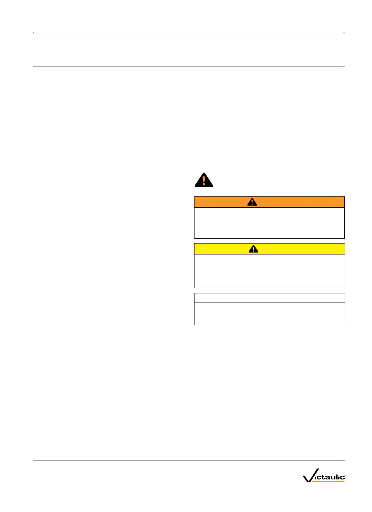
HAZARD IDENTIFICATION
Definitions for identifying the various hazard levels are
provided below. When you see this symbol, be alert to the
possibility of personal injury. Carefully read and fully
u nderstand the message that follows.
WARNING
• Theuseoftheword“WARNING”identifiesthepresence
ofhazardsorunsafepracticesthatcouldresultindeathor
seriouspersonalinjuryifinstructions,includingrecommended
precautions,arenotfollowed.
CAUTION
• Theuseoftheword“CAUTION”identifiespossiblehazardsor
unsafepracticesthatcouldresultinpersonalinjuryandprod-
uctorpropertydamageifinstructions,includingrecommended
precautions,arenotfollowed.
NOTICE
• Theuseoftheword“NOTICE”identifiesspecialinstructions
thatareimportantbutnotrelatedtohazards.
REV_B
FireLockNXT™AutoConvertPreactionValve
SERIES 769
PreactionElectricAutoConvertDryTrim
I-769P.AC/ELEC
INSTALLATION,MAINTENANCE,ANDTESTINGMANUAL
www.victaulic.com
VICTAULIC IS A REGISTERED TRADEMARK OF VICTAULIC COMPANY. © 2009 VICTAULIC COMPANY. ALL RIGHTS RESERVED. PRINTED IN THE USA.
I-769P.AC/ELEC_1

 Loading...


