VALVE/TRIMINSTALLATION
1. Make sure the trim drawing matches the system’s requirements.
CAUTION
Makesurethefoamspacerisremovedfrom•
insidethevalvebodybeforeattemptingto
installthevalve.
Failuretofollowthisinstructioncouldcause
impropervalveoperation,resultinginpersonal
injuryand/orpropertydamage.
2. Remove all plastic caps and foam spacers from the valve.
3. Apply a small amount of pipe joint compound or Teflon* tape to
the external threads of all threaded pipe connections. DO NOT get
any tape, compound, or other foreign material into the valve body,
pipe nipples, or valve openings.
CAUTION
Makesurenoforeignmaterialgetsintothevalvebody,pipe•
nipples,orvalveopenings.
IfusinganymaterialotherthanTeflontape,useextracaution•
sothatnomaterialgetsintothetrim.
Failuretofollowtheseinstructionscouldcauseimpropervalve
operation,resultinginpersonalinjuryand/orpropertydamage.
4. Install the valve, trim, and accessories per the trim drawing.
5. Supply pressure to the diaphragm charge line by providing an
uninterrupted source of water from upstream of the main control
valve.
* Teflon is a registered trademark of the DuPont Company
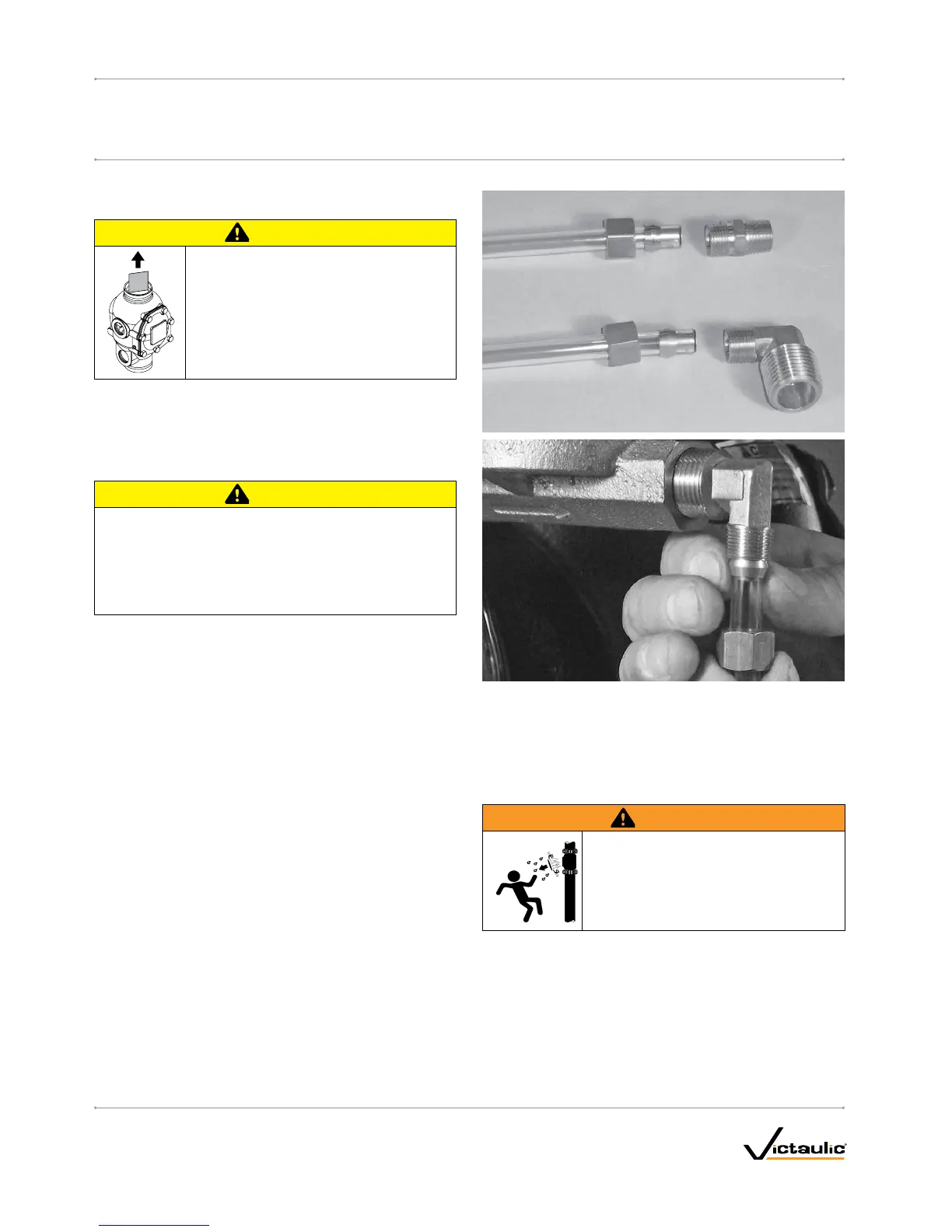
COMPRESSIONFITTINGANDTUBEINSTALLATION
Compression fittings and tubes are provided for connection from the
outlet of the auto drain, drip check, and actuator to the drip cup or
drain. These compression fittings and tubes must be installed, in accor-
dance with the trim drawing provided. NEVER insert a plug into the out-
let of the auto drain, drip check, or actuator in place of the compression
fitting/tube.
HYDROSTATIC TESTING
WARNING
Ifairtestingisrequired,DONOTexceed•
50psi/345kPa/3.4Barairpressure.
Failuretofollowthisinstructioncouldresult
inseriouspersonalinjuryand/orproperty
damage.
The Victaulic Series 769 FireLock NXT Deluge Valve is UL Listed and
FM Approved for a maximum working pressure of 300 psi/
2065 kPa/20.7 Bar and is factory tested to 600 psi/4135 kPa/41.4 Bar for
all sizes. The valve can be hydrostatically tested against the clapper at
200 psi/1380 kPa/13.8 Bar or 50 psi/345 kPa/3.4 Bar above the normal
water supply pressure (2-hour limited time period) for acceptance by
the authority having jurisdiction.
I-769D_14
FireLockNXT™DelugeValve
SERIES 769
I-769D
INSTALLATION,MAINTENANCE,ANDTESTINGMANUAL
www.victaulic.com
VICTAULIC IS A REGISTERED TRADEMARK OF VICTAULIC COMPANY. © 2007 VICTAULIC COMPANY. ALL RIGHTS RESERVED. PRINTED IN THE USA.
REV_D

 Loading...


