From Water
Supply
2
3
1
11
19
20
14
13
16
18
17
22
15
6
21
12
8
4
7
9
10
From System
Air Feed
To Pilot
Line
To System
22
5
A
Location
A
To Drip
Cup
Location
A
To Drip Cup
Location
A
To Drip Cup
Location
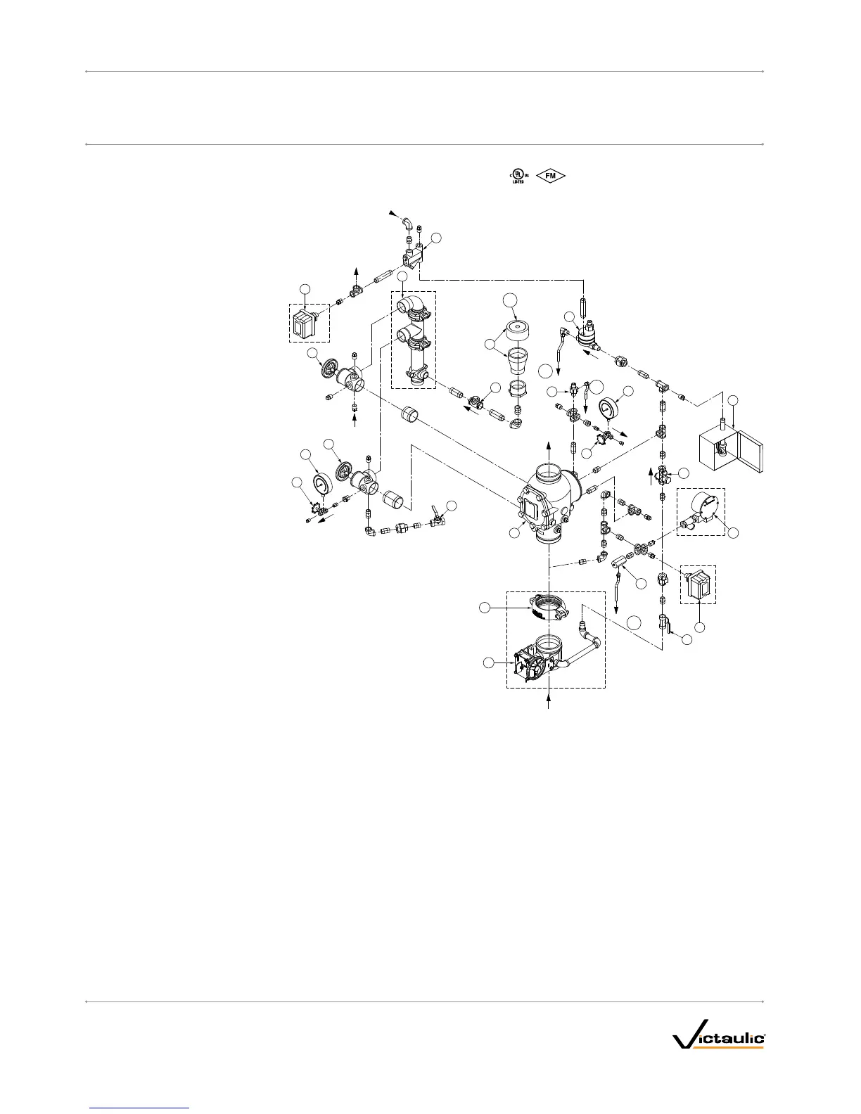
Note 1
Bill of Materials
1 Series 769 FireLock NXT Deluge Valve
2 FireLock Rigid Coupling (Optional/Sold
Separately – Comes Standard when VQR
Assembly is Ordered)
3 Water Supply Main Control Valve
(Optional/Sold Separately – Comes Standard
when VQR Assembly is Ordered)
4 Drain Swing Check Valve
5 Drip Cup with Cap
6 Alarm Pressure Switch (Optional/Sold
Separately – Comes Standard when VQR
Assembly is Ordered)
7 Series 729 Drip Check Valve
8 Diaphragm-Charge-Line Ball Valve
(Normally Open)
9 3-in-1 Strainer/Check/Restrictor
Assembly
10 Series 760 Water Motor Alarm
(Optional/Sold Separately)
11 Alarm Test Ball Valve
12 Diaphragm-Charge-Line Pressure
Gauge (0-300 psi/0-2068 kPa/0-20.7Bar)
13 Series 749 Auto Drain
14 Series 776 Low-Pressure Actuator
15 Air Manifold
16 Air Supervisory Pressure Switch
(Optional/Sold Separately – Comes Standard
when VQR Assembly is Ordered)
17 Water Supply Main Drain Valve - Flow Test
18 Water Supply Pressure Gauge
(0-300 psi/0-2068 kPa/0-20.7 Bar)
19 Drain Connection Kit (Optional/Sold
Separately – Comes Standard when VQR
Assembly is Ordered)
20 System Main Drain Valve
21 Series 755 Manual Pull Station
22 Gauge Valve
NOTE 1: Connection point for the Series 75D Water Column Device Kit
For information regarding installation of the Series 7C7 Air Maintenance/Compressor Assembly (not shown), refer to the instructions supplied with the
product.
I-769D_4
FireLockNXT™DelugeValve
SERIES 769
I-769D
INSTALLATION,MAINTENANCE,ANDTESTINGMANUAL
www.victaulic.com
VICTAULIC IS A REGISTERED TRADEMARK OF VICTAULIC COMPANY. © 2007 VICTAULIC COMPANY. ALL RIGHTS RESERVED. PRINTED IN THE USA.
REV_D

 Loading...


