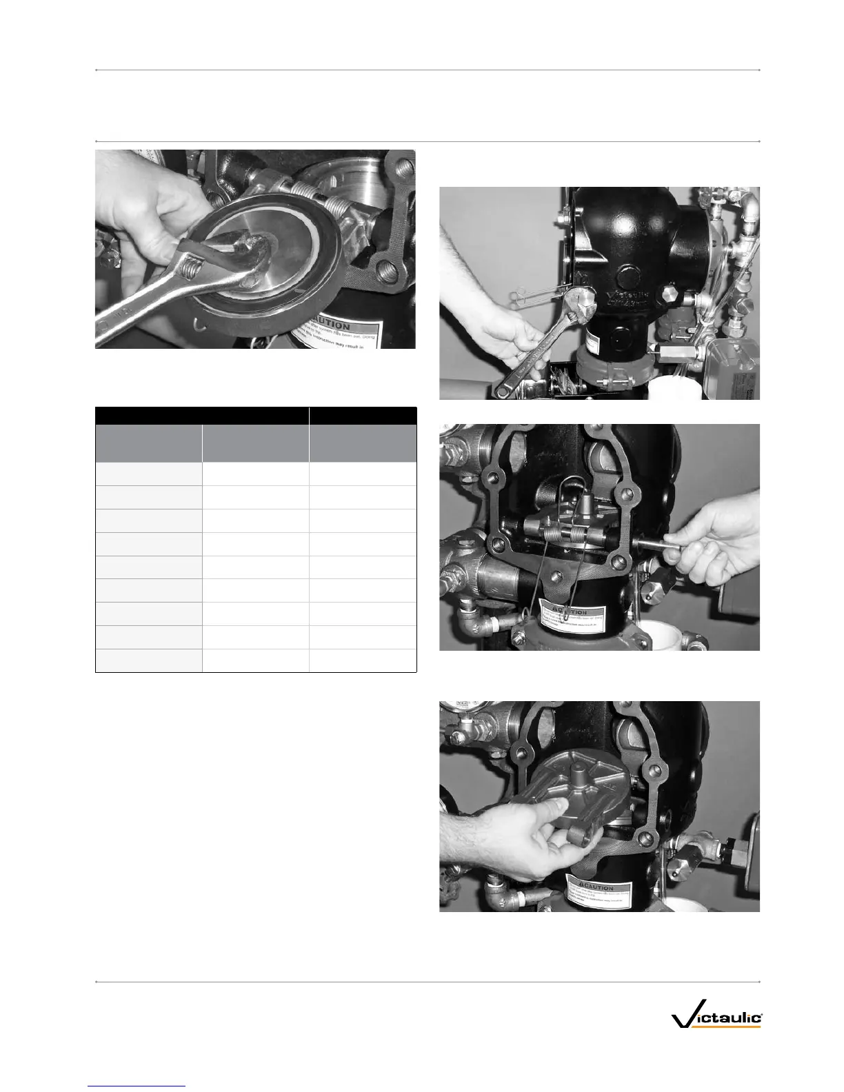
11. Tighten the seal-assembly bolt/bolt seal to the torque value, listed
in the table below, to ensure a proper seal.
REQUIREDSEAL-ASSEMBLYBOLT/BOLTSEALTORQUES
Size Torque
NominalSize
inches
Actual
OutsideDiameter
inches
mm
ft-lbs
N•m
1 ½
1.900 40
48.3 5
2
2.375 40
60.3 5
2 ½
2.875 90
73.0 10
76.1 mm
3.000 90
76.1 10
3
3.500 90
88.9 10
4
4.500 110
114 . 3 12
165.1 mm
6.500 160
165.1 18
6
6.625 160
168.3 18
8
8.625 160
219.1 18
12. Replace the cover plate by following the “Installing the Cover Plate
Gasket and Cover Plate” section.
13. Place the system back in service by following the “Placing the
System in Service” section.
REMOVINGANDREPLACINGTHECLAPPERASSEMBLY
1. Perform steps 1 – 12 of the “Required Internal Inspection” section.
2. Remove the clapper shaft bushings from the valve body.
3. Remove the clapper shaft. NOTE: As the shaft is being removed,
the clapper spring will drop out of position. Keep the clapper
spring for re-installation.
4. Remove the clapper from the valve body.
I-769D_39
FireLockNXT™DelugeValve
SERIES 769
I-769DINSTALLATION,MAINTENANCE,ANDTESTINGMANUAL
www.victaulic.com
VICTAULIC IS A REGISTERED TRADEMARK OF VICTAULIC COMPANY. © 2007 VICTAULIC COMPANY. ALL RIGHTS RESERVED. PRINTED IN THE USA.
REV_D

 Loading...


