INTRODUCTION
The following instructions are a guide for proper installation of Victaulic Series 769 FireLock NXT Deluge Valves. These instructions involve pipe that
is properly prepared and grooved in accordance with current Victaulic specifications.
NOTICE
Drawingsand/orpicturesinthismanualmaybeexaggeratedforclarity.•
Thisproductandthisinstallation,maintenance,andtestingmanualcontaintrademarks,copyrights,and/orpatentedfeaturesthatarethe•
exclusivepropertyofVictaulic.
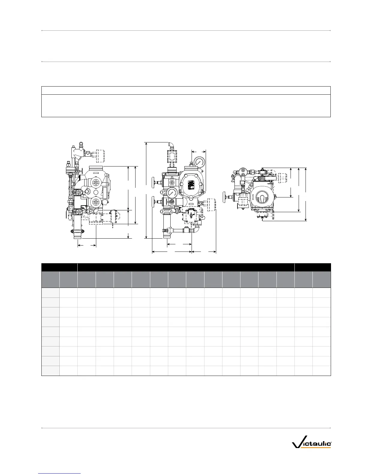
TRIMDIMENSIONS
THE4-INCH/114.3-MMCONFIGURATIONISSHOWNBELOW1–2-INCH/48.3–60.3-MMCONFIGURATIONSCONTAIN-INCH/19-MMDRAINVALVES.
2–3-INCH/73.0–88.9-MMCONFIGURATIONSCONTAIN1-INCH/31-MMDRAINVALVES.4–8-INCH/114.3–219.1-MMCONFIGURATIONSCONTAIN2-INCH/50-MMDRAINVALVES.
Size Dimensions–inches/mm
Aprx.WeightEa.
lbs/kg
Nominal
Sizeinches
mm
Actual
Out.Dia.
inches
mm A A1* B C D D1* E E1* F H J K
Without
Trim
With
Trim
1 ½ 1.900 9.00 16.43 28.50 13.75 12.50 15.00 5.25 8.50 9.25 3.04 9.17 6.98 16.7 43.0
40 48.3 228.60 417. 32 723 349 317 381 133 215 234 77. 21 232.91 17 7.29 7. 6 19.5
2 2.375 9.00 16.43 28.50 13.75 12.50 15.00 5.25 8.50 9.25 3.04 9.17 6.98 17. 0 43.0
50 60.3 228.60 417. 32 723 349 317 381 133 215 234 7 7.21 232.91 17 7. 29 7. 7 19.5
2 ½ 2.875 12.61 16.50 32.25 13.50 13.50 17. 50 5.25 9.00 9.25 3.90 10.50 6.93 41.0 65.0
65 73.0 320.29 419.10 819 342 342 444 133 228 234 99.06 266.70 176.02 18.7 29.5
76.1 mm
3.000 12.61 16.50 32.25 13.50 13.50 17. 50 5.25 9.00 9.25 3.90 10.50 6.93 41.0 65.0
76.1 320.29 419.10 819 342 342 444 133 228 234 99.06 266.70 176.02 18.7 29.5
3 3.500 12.61 16.50 32.25 13.50 13.50 17. 50 5.25 9.00 9.25 3.90 10.50 6.93 41.0 65.0
80 88.9 320.29 419.10 819 342 342 444 133 228 234 99.06 266.70 176.02 18.7 29.5
4 4.500 15.03 19.78 33.50 15.00 15.75 20.50 5.50 9.00 10.75 6.25 9.62 8.46 59.0 95.0
100 114 . 3 381.76 502.41 850 381 400 520 139 228 273 158.75 244.34 214.88 26.7 43.0
165.1 mm
6.500 16.00 22.00 33.75 15.50 16.75 22.00 6.00 8.50 11. 2 5 6.20 9.62 8.84 80.0 116 . 0
165.1 406.40 558.80 857 393 425 558 152 215 285 15 7.4 8 244.34 224.53 36.2 52.6
6 6.625 16.00 22.00 33.75 15.50 16.75 22.00 6.00 8.50 11. 2 5 6.20 9.62 8.84 80.0 116 . 0
150 168.3 406.40 558.80 857 393 425 558 152 215 285 15 7.4 8 244.34 224.53 36.2 52.6
8 8.625 17. 50 22.94 33.50 16.75 19.75 25.25 7. 0 0 8.75 12.75 6.05 9.40 10.21 122.0 158.0
200 219.1 444.50 582.67 850 425 501 641 177 222 323 153.67 238.76 259.33 55.3 71.6
NOTES:
The drawings shown above reflect the dry pilot trim with Series 776 Low-Pressure Actuator. In addition, these dimensions can be applied to hydraulic (wet
pilot) release and electric release trim.
The “A” dimension coupling and the optional sensor switch are not shown for clarity.
Components shown as dotted lines denote optional equipment
* Measurements denoted with an asterisk take optional equipment into account.
Optional drain connection kit is shown for reference and takeout dimensions.
NOTE: For VdS trim, add 3.75 inches/95mm to
the D, D1, and F dimensions to account for the
additional water motor alarm shutoff valve.
I-769D_3
FireLockNXT™DelugeValve
SERIES 769
I-769DINSTALLATION,MAINTENANCE,ANDTESTINGMANUAL
www.victaulic.com
VICTAULIC IS A REGISTERED TRADEMARK OF VICTAULIC COMPANY. © 2007 VICTAULIC COMPANY. ALL RIGHTS RESERVED. PRINTED IN THE USA.
REV_D

 Loading...


