22. If water is flowing from the drip check, close the water sup-
ply main control valve, and start over at step 1. Refer to the
“Troubleshooting” section.
23. Open the water supply main control valve fully.
24. Record the system air pressure (for pneumatic [dry pilot] release
systems) and the water supply pressure.
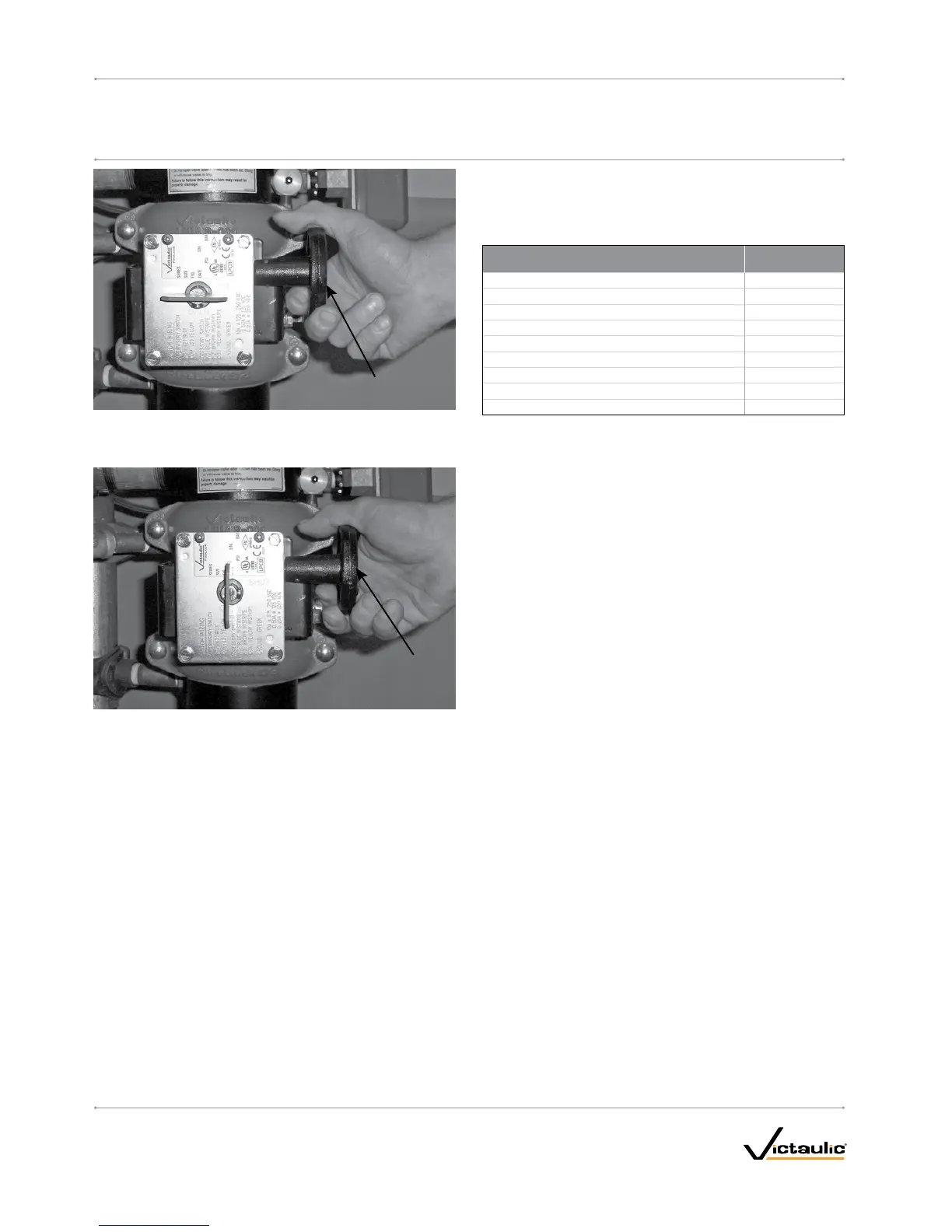
25. Confirm that all valves are in their normal operating positions (refer
to the table below).
Valve
NormalOperating
Position
Diaphragm-Charge-Line Ball Valve Open
Alarm Test Ball Valve Closed
Water Supply Main Control Valve Open
Water Supply Main Drain Valve Closed
System Main Drain Valve Closed
Alarm Line Ball Valve (VdS Trim Only) Open
Slow-Fill Ball Valve of the Victaulic AMTA (if applicable) Open
Fast-Fill Ball Valve of the Victaulic AMTA (if applicable) Closed
Water Motor Alarm Shutoff Valve (VdS Trim Only) Open
26. Notify the authority having jurisdiction, remote station alarm
monitors, and those in the affected area that the system is in
s e r v i c e .
ONAWEEKLYBASIS,WHENTHEVALVEISRESETAFTERAN
OPERATIONALTEST(ORAFTERANYSYSTEMOPERATION): The
low-body drain valve and any low-point drain valves should be partially
opened and then closed to drain water that might be present in the
riser. Continue this procedure until all water is released.
I-769D_22
FireLockNXT™DelugeValve
SERIES 769
I-769DINSTALLATION,MAINTENANCE,ANDTESTINGMANUAL
www.victaulic.com
VICTAULIC IS A REGISTERED TRADEMARK OF VICTAULIC COMPANY. © 2007 VICTAULIC COMPANY. ALL RIGHTS RESERVED. PRINTED IN THE USA.
REV_D
 Loading...


