66250754-EN - V1.0 - 18/02/19
- 13 -
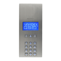
4000 Series GSM Audio Intercom - Technical Manual
4000 Series GSM Audio Intercom with Proximity
NO Normally open relay contact.
Relay contacts:
3A@24Vdc
3A@120Vac
C Common relay contact.
NC Normally closed relay contact.
0V
RS485 bus terminals for permanent connection to a PC, also used to network with Art.4903 codelock and Art.4850R
proximity reader (up to 8 devices max.).
B
A
a - g
Button matrix for connecting up to 50 call buttons, PTE, and auxiliary inputs.
The PTE (push to exit button) connects across g-6.
Auxiliary 1 input connects across g-5 (activates AO1 when set to mode 01).
Auxiliary 2 input connects across g-4 (sends SMS message to master telephone number).
1 - 8
JP2 Nameplate window LED illumination adjustment. JP2 position A = LED bright,
JP2 position B = LED low, JP2 removed = LED disabled.
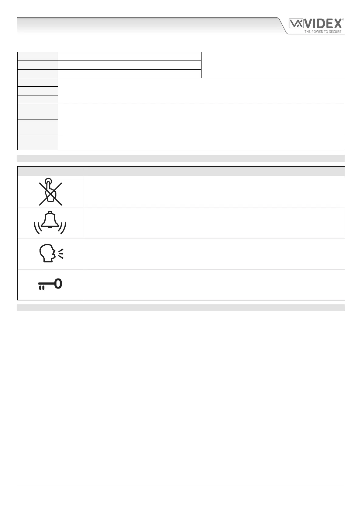
CALL PROGRESS LED’S
LED (sign) Description
The busy LED when illuminated, indicates that it is not possible to make a call because a call or a
conversation is in progress. The LED will be OFF when the system is in standby. If there is power on
the GSM intercom and the Art.432 antenna is not connected this LED will ash continuously until the
antenna is connected. The LED will ash while connecting to a network.
The call LED when illuminated, indicates that the call from the GSM intercom panel is in progress. The
LED will switch OFF when the call is answered or after the call time expires.
The speak LED when illuminated, indicates that it is possible to speak because the call has been
answered. The LED will switch OFF at the end of a conversation when the telephone/mobile that has
been dialled hangs up or at the end of the call time.
The open LED when illuminated, indicates that the door lock (GSM relay) has been operated. It will
switch OFF at the end of the programmed “door opening” time. The LED will also illuminate and operate
the relay if a programmed key fob is presented to the onboard proximity reader (nameplate window).
TECHNICAL SPECIFICATION
Working Voltage: : 12 - 24Vdc or ac +/- 10%
Standby Current: : approx. 60mA
Max. Current: approx. 500mA (max.)
Call Buttons: up to 50 (max.)
Telephone Numbers per Button: 4 telephone numbers (1 primary, 3 diverts)
Dial to Open Numbers: up to 1000 (max.)
Proximity Access (fobs/cards): up to 1000 users (max.)
Coded Access: up to 400 permanent codes and 32 temporary codes (when used with Art.4903 via RS485 bus)
Call Progress LED's: 4 (busy, call, speak and open)
Programming Method: SMS messaging or PC software
RS485 Bus Connection: A, B and 0V
Push to Exit Input: 1 (push-to-make across terminals g-6)
Auxiliary Inputs: 2 (AO1 = across terminals g-5, AO2 = across terminals g-4)
Auxiliary Outputs: 2 (open collector output, switched 0V, 150mA max.)
Dry Contact Relay: C, NO and NC, 3A @ 24Vdc, 3A @ 120Vac
Event Logging: up to 4000 events (unlimited when using remote logging facility)
USB Port: micro USB
Timebands: 1 call button timeband; 10 access control and 10 free access timebands
Working Temperature: -10 +50
o
C
Art. 4810 Technical Information
terminals continued...

 Loading...