66250754-EN - V1.0 - 18/02/19
- 14 -
4000 Series GSM Audio Intercom - Technical Manual
4000 Series GSM Audio Intercom with Proximity
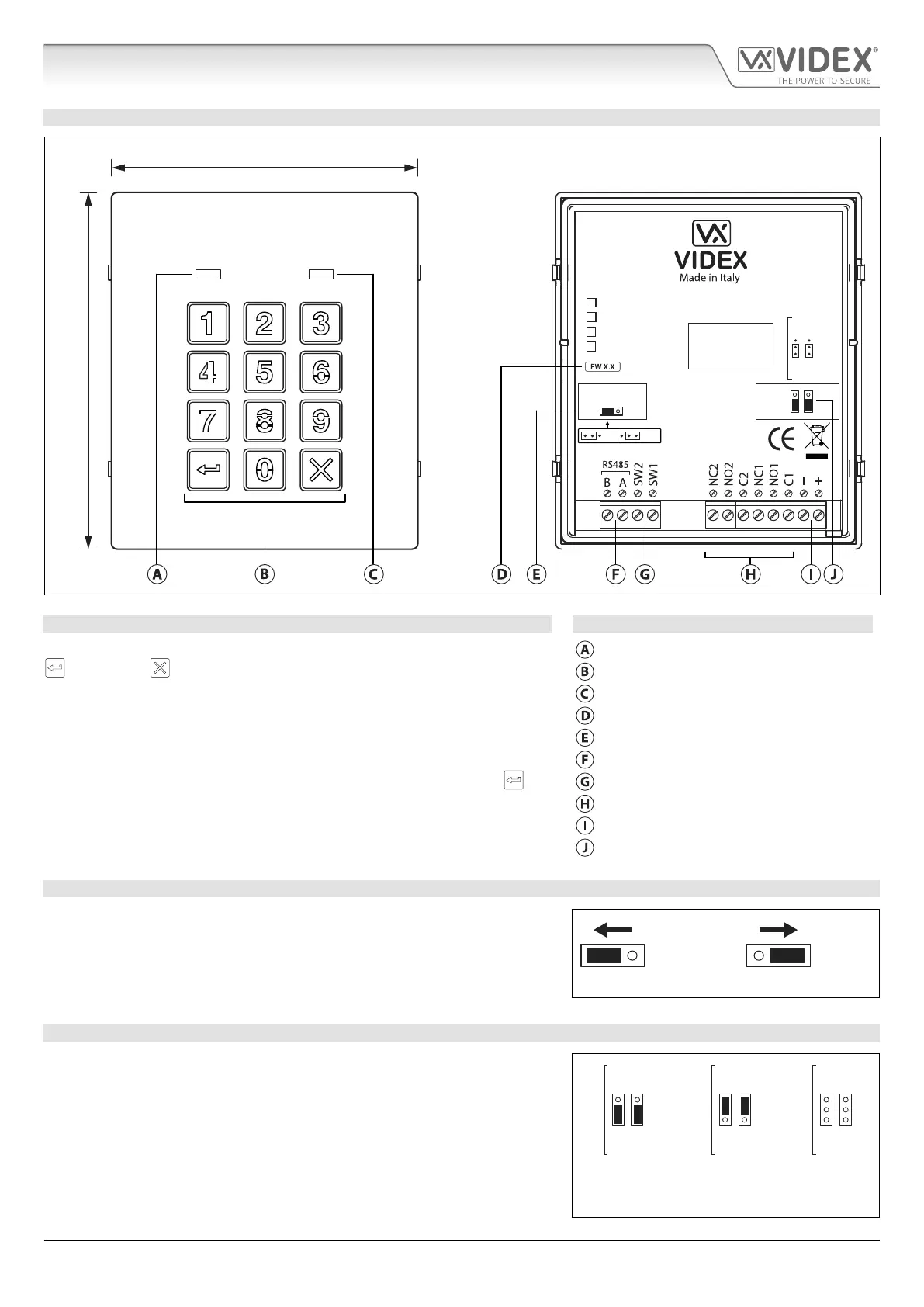
ART. 4903 CODELOCK MODULE
OFFON
RS485 BUS TERMINATION
4903
STEEL
ALI
HIGH BRASS
MATTE
MOV
NO1 NC1
NO2 NC2
Note: Remove MOV
jumper completely
when using a relay to
trigger a gate controller.
103mm
120mm
Fig. 11
DESCRIPTION LEGEND
The module features 12 stainless steel buttons, backlit in blue (keys 0 - 9, ENTER
and CLEAR ), 2 LED’s (green LED = data, red LED = status indication)
for progress information during use and programming and a stainless steel or
aluminium front plate, see Fig.11. With two integral relays (RLY1 and RLY2) each
with common (C), normally open (NO) and normally closed (NC) connections
and two switched 0V push to exit inputs SW1 and SW2 to enable the external
triggering of the relays. Key presses are signalled acoustically while each button
press has a tactile feel. Entering the correct code followed by ENTER will
activate the relevant relay.
Data LED (green)
Backlit (blue) key buttons
Status indication LED (red)
Current rmware version (FW X.X)
RS485 bus termination jumper (JP1)
RS485 bus terminals
PTE terminals (SW1 and SW2)
Relay terminals (RLY1 and RLY2)
Power input terminals
Back EMF protection (JP2 and JP3)
RS485 BUS TERMINATION JUMPER JP1
The jumper JP1 on the rear of the keypad sets the RS485 bus termination when
connected to the Art.4810 GSM PRO or other RS485 devices. By default the
jumper is set to the ON position (across to the left). When more than one RS485
device is connected to the keypad in line on the RS485 bus terminals then the
jumper can be set to the OFF position (across to the right) and only set to the
ON (closed) position on the end of line device, see Fig.12.
ON OFF
Fig. 12
RELAY BUILTIN BACK EMF PROTECTION JP2 AND JP3
The Art.4903 includes selectable back EMF protection (metal oxide varistors)
jumpers JP2 and JP3 for each relay (marked MOV) and are used to select the
protection type. When using a fail secure lock with connections C & NO the
jumper should be in the NO position. When using a fail open (safe) lock with
connections C & NC the jumper should be in the NC position, as shown in
Fig.13. When using the codelock to trigger a gate controller or another third
party controller the jumper should be removed completely (this disables the
protection on the relay).
NC2
NC1
NO2
NO1
MOV
NC2
NC1
NO2
NO1
MOV
NC2
NC1
NO2
NO1
MOV
NO position for fail
secure lock release
NC position for fail
safe lock release
remove jumpers
for gate controls
Fig. 13
Art. 4903 Technical Information

 Loading...