66250754-EN - V1.0 - 18/02/19
- 15 -
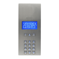
4000 Series GSM Audio Intercom - Technical Manual
4000 Series GSM Audio Intercom with Proximity
PROGRAMMING AS A STANDALONE KEYPAD
When using the Art.4903 as a standalone keypad the programming is the same as the programming of an Art.4800M keypad
(refer to programming guide and owchart below). All programming is carried out using the keypad. The programming menu is
protected by an ENGINEER’S CODE, the factory default of which is six times 1 (“111111”). This code can be changed to any 4 to 8
digit ENGINEER’S CODE during the programming and is used to gain entry to the programming menu only.
Each relay (RLY1 and RLY2) can be programmed with a 4 - 8 digit access code (one code per relay) and will activate the respective
relay for the programmed relay time (01 - 99 seconds or 00 for latching). The access code programmed is stored in the keypads
internal memory.
PROGRAMMING GUIDE
• Enter the ENGINEER’S CODE: rst time type six times 1 (111111
factory default) and press ENTER
to conrm, (the red LED
will illuminate);
• Conrm ENGINEER’S CODE: re-type the same code again or
type a new code (4 to 8 digits) then press ENTER
to conrm,
(melody);
• Enter the code (4 to 8 digits) to enable RELAY 1 then press
ENTER
to conrm, (melody);
• Enter the RELAY 1 operation time (2 digits 01 to 99, i.e. 05 = 5
seconds, 00 = latch) then press ENTER
to conrm, (melody);
• Enter the code (4 to 8 digits) to enable RELAY 2 then press
ENTER
to conrm, (melody);
• Enter the RELAY 2 operation time (2 digits 01 to 99, i.e. 05 = 5
seconds, 00 = latch) then press ENTER
to conrm, (melody);
• Press ENTER
twice again to exit programming (melody);
• The system is ready to use (the red LED will switch OFF).
PROGRAMMING NOTES
• Pressing the ENTER
button twice during the programming
process, without changing any parameters, will exit from the
programming menu.
• When entering a relay code it must be dierent from the
ENGINEER'S CODE.
• To latch the relay type in the access code then press ENTER
to conrm. To unlatch the relay type in the same access code
again then press ENTER
to conrm.
ENTER THE
“ENGINEER’S CODE”
CONFIRM
OR CHANGE
“ENGINEER’S CODE”
ENTER
“ACCESS 1 CODE”
ENTER
“ACCESS 1 TIME”
ENTER
“ACCESS 2 CODE”
ENTER
“ACCESS 2 TIME”
SYSTEM
READY TO USE
Press ENTER
(red LED ON)
Press ENTER
(melody)
Press ENTER
(melody)
Press ENTER
(melody)
Press ENTER
(melody)
Press 1 six times
“111111”
(factory default)
Press 1 six times
“111111” again or
type new engineer’s
code (4 to 8 digits)
Type code to enable
relay 1 (4 to 8 digits)
Type code to enable
relay 2 (4 to 8 digits)
Two digits (01 to 99)
i.e. 05 = 5 seconds,
00 = latching
Two digits (01 to 99)
i.e. 05 = 5 seconds,
00 = latching
red LED OFF
Press ENTER
twice again to exit
(melody)
Press ENTER
(melody)
RESETTING THE CODELOCK BACK TO FACTORY DEFAULTS
Follow the steps below to reset the codelock to factory defaults:
1. Remove/disconnect the power from the Art.4903 codelock;
2. Short out terminals - and SW2, see Fig.14;
3. Press and hold down the ENTER
button and keep pressed
down while the power is switched back ON;
4. When power is restored to the codelock wait for the module
to emit a beep and wait for the red status LED (Fig.11,
) to
stop ashing;
5. Release the ENTER
button then remove the short between
terminals - and SW2, see Fig.15;
6. The ENGINEER'S CODE has been reset back to the factory
default, 6x1 ("111111"), relays reset to 5 seconds and internal
access codes for RLY1 and RLY2 cleared.
Fig. 14
Fig. 15
Art. 4903 Technical Information

 Loading...