66250754-EN - V1.0 - 18/02/19
- 12 -
4000 Series GSM Audio Intercom - Technical Manual
4000 Series GSM Audio Intercom with Proximity
Art. 4810 Technical Information
ART. 4810 GSM PRO MODULE
Internal jumper JP2
Nameplate LED illumination adjustment
R02A
RS485
GSM4K-3.0.2
103mm
120mm
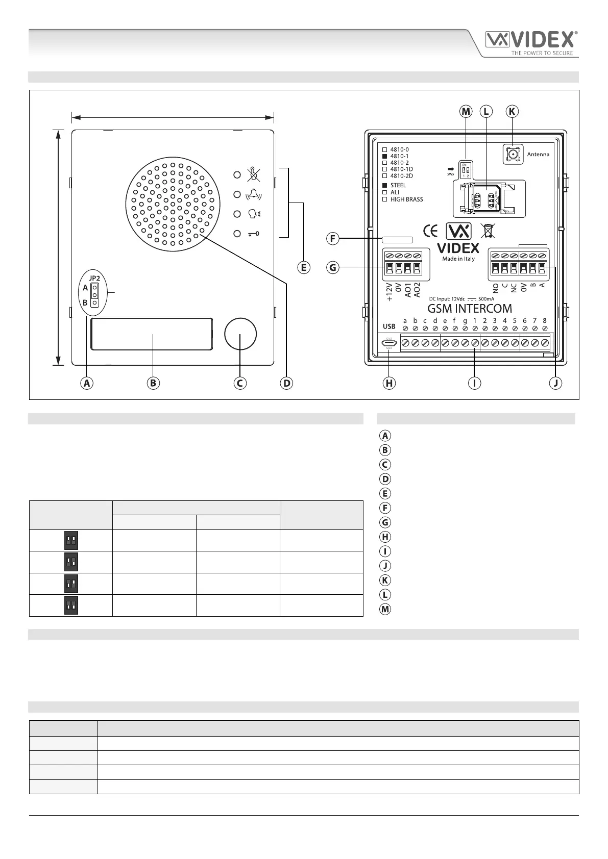
Fig. 10
SPEAKER VOLUME ADJUSTMENT DIPSWITCH SETTINGS LEGEND
There are 2 dip-switches located on the back of the GSM module next to the
antenna connection, see Fig.10. They can be used to adjust the volume from
the door intercom speaker (see table below). Additionally, the volume can also
be adjusted during a call electronically via the telephone keypad (refer to user
command table on page 66).
Internal nameplate LED jumper (JP2)
Nameplate and proximity access reader
Call button
Intercom speaker
Call progress LED's
Dip-Switch
Dip-Switch Status
Gain (dB)
Current rmware version (GSM4K X.X.X)
Dip No.1 Dip No.2
Power input and auxiliary terminals
1 2
ON
ON ON 6
Micro USB connection
Button matrix terminals
1 2
ON
ON OFF 12
Relay output and RS485 bus terminals
1 2
ON
OFF ON 18
Antenna connection
SIM card holder
1 2
ON
OFF OFF 23.5
Speaker volume dip-switches
NAMEPLATE ILLUMINATION JUMPER JP2
The nameplate LED illumination jumper JP2 is located behind the GSM module’s front facia, as shown in Fig.10. To access the
jumper the facia must be removed and the jumper can be adjust as required. When JP2 is set in position A (upper 2 pins) the LED
is set for bright illumination, when JP2 is set in position B (lower 2 pins) the LED is set for low illumination and if JP2 is completely
removed this will disable the nameplate LED’s.
TERMINAL CONNECTIONS
Terminal Description
+12V 12 - 24Vdc or ac power.
0V 0V ground power.
AO1 Auxiliary output 1 (open collector, 150mA max.).
AO2 Auxiliary output 2 (open collector, 150mA max.).

 Loading...