66250754-EN - V1.0 - 18/02/19
- 6 -
4000 Series GSM Audio Intercom - Technical Manual
4000 Series GSM Audio Intercom with Proximity
DESCRIPTION
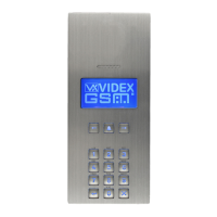
A system comprises of an intercom panel, power supply, SIM card (SIM card not provided by Videx) and antenna. The intercom panel
is part of the Videx 4000 series modular design allowing it to be customised to the installation requirements for example including
coded access, proximity access or including the correct number of call buttons (up to 50 call buttons).
ART. 4810 GSM PRO INTERCOM AVAILABLE VERSIONS
The intercom panel can include any of the modules from the 4000 series range and uses the standard 4000 series surface and
ush mounting frames. The GSM PRO module is however essential and includes all the GSM communication electronics, SIM card
(supplied separately) and connections. The intercom module is available in a 0 button, 1 button, 2 button and 4 button conguration
(with all onboard buttons internally wired), as shown in Fig.1 along with their part numbers.
Art. 4810-0,
Art. 4810-0/3G
Art. 4810-1
Art. 4810-1/3G
Art. 4810-2
Art. 4810-2/3G
Art. 4810-1D
Art. 4810-1D/3G
Art. 4810-2D
Art. 4810-2D/3G
Fig. 1
EXTENSION BUTTON MODULES
The GSM intercom module will accept up to 50 call buttons. Any of the standard 4000 series button modules can be used as shown
in Fig.2 along with their part numbers. Please note that button 1 is in the bottom right corner of the module counting up.
Art. 4842 Art. 4843 Art. 4844 Art. 4845 Art. 4842D Art. 4843D Art. 4844D Art. 4845D
Fig. 2
Button connections to the GSM module are shown in Fig.4 on page 7 (only the wiring of the button matrix is shown). It is important
to take care when using additional button modules with a GSM intercom module which also has onboard buttons. For example, an
intercom module with one button means the extension button module used must start wiring from button 2, an intercom module
with 2 buttons means the extension button module used must start wiring from button 3 and so on.
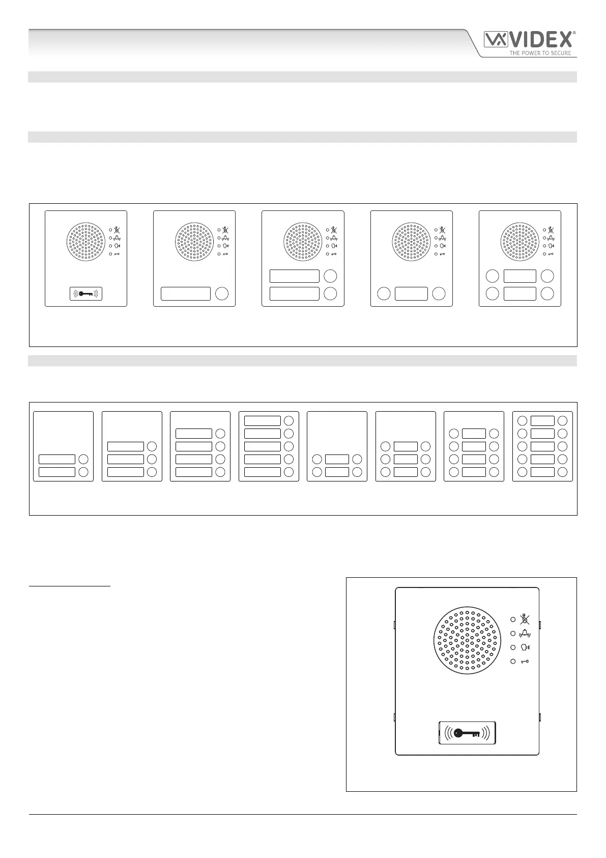
IMPORTANT NOTE: When extension button modules are being used
on systems where proximity access is required and the Art.4810-0 GSM
PRO module is used, the location of the onboard proximity reader is on
the front of the main GSM PRO module below the speaker, as shown in
Fig.3.
Standard versions of the GSM PRO (e.g. Art.4810-0 etc.) works on a 2G
network. A 3G variant is also available (see Fig.1 above) that works on a
3G network, sux /3G to the part no. (e.g. Art.4810-1/3G etc.).
Art. 4810-0, Art.4810-0/3G
Fig. 3
1 1 13 13
24
2
1
2
3
4
5
6
7
8
9
10
System Components and Available Versions

 Loading...