66250754-EN - V1.0 - 18/02/19
- 16 -
4000 Series GSM Audio Intercom - Technical Manual
4000 Series GSM Audio Intercom with Proximity
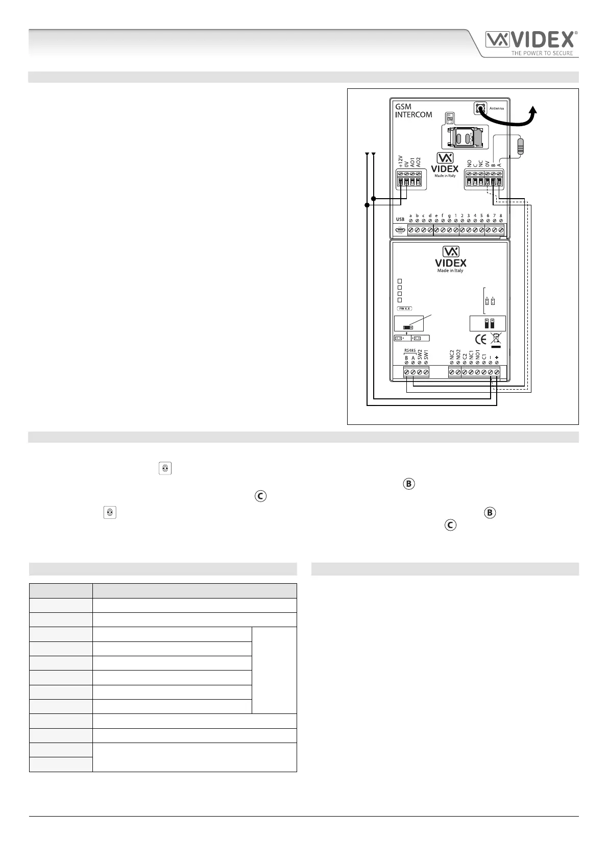
PROGRAMMING WHEN INTEGRATED WITH THE GSM PRO ART.4810 MODULE VIA THE RS485 BUS CONNECTIONS
The Art.4903 can also be programmed using the GSMSK PC software
(refer to the manual: GSMSK_66251720_EN_V2-0 or later) and also
via text messaging (refer to notes programming the GSM intercom on
pages 37 - 61). When wired directly to the GSM PRO module using the
RS485 bus connections, see Fig.16, additional access code features of
the GSM PRO module become available which include:
• program up to 400 permanent access codes (000 - 399);
• assign any of the 400 access codes to an access level (0 - 9) and relay;
• program up to 32 temporary access codes;
• allocate any of the 32 temporary codes to a specic time period
(between 1 - 255 hours) after which time the code will be deleted;
• assign any of the codes, whether permanent or temporary, to trigger
any or a combination of the two relays (RLY1 and/or RLY2).
Also refer to notes RS485 network connection on pages 27 - 29.
The access codes can be 4 - 8 digits in length and are stored in the GSM
PRO module’s memory not the keypad.
Even when the Art.4903 is connected to the GSM PRO with the RS485 bus
connection any access codes programmed directly using the keypad,
following the programming owchart on page 15, for relays 1 and 2 (as if
the keypad were programmed as a standalone keypad) will still operate
the respective relay.
The RS485 connection also allows the keypad to be networked with other
Art.4903 keypads and Art.4850R proximity readers where each module
requires a unit ID to be setup (see below) up to a total of 8 devices.
Art.4810
RS485 bus
termination
jumper in
ON position
OFFON
RS485 BUS TERMINATION
4903
STEEL
ALI
HIGH BRASS
MATTE
MOV
NO1 NC1
NO2 NC2
RS485 bus cable
(2 core twisted or CAT-5 where: 1 core = A, 1 core = B, 1 pair = 0V/GND)
+12Vdc power
from HDR-15-12
To Antenna
120Ω resistor
tted across A & B
unless connected
to an Art.481
Fig. 16
SETTING UP THE UNIT ID OF THE KEYPAD ID 1 8
1. First disconnect the power from the Art.4903 keypad, then short out terminals - and SW2, see Fig.14;
2. Press and hold down the 0
button, keeping it pressed while the power is switched back ON;
3. When power is restored to the keypad the backlit key buttons will illuminate (Fig.11,
). Wait for the keypad to emit a low
level tone then wait for the red status LED (Fig.11, ) to switch ON;
4. Release the 0
button then enter the unit ID required for the Art.4903 (1 - 8) using the keypad (Fig.11, ). The red status
LED will switch OFF and the keypad will play a short melody. Observe the red status LED (Fig.11, ) as this will ash as many
times as the unit ID being set (e.g. if the unit ID is set to ID.8 the red status LED will ash 8 times);
5. After the red status LED stops ashing remove the short between terminals - and SW2, see Fig.15, the unit ID has been set.
TERMINAL CONNECTIONS TECHNICAL SPECIFICATION
Connection Description Working voltage: 12V - 24Vac/dc +/- 10%
+ 12-24V AC or DC power input Current Consumption: 20mA (standby); 70mA (max.)
- 0V power input Number of relays: 2, RLY1 and RLY2 (C, NC and NO)
C1 Relay 1 common connection
Relay contacts:
3A @ 24Vac/dc
(max.)
Relay current ⁄ voltage: 3A @ 24Vac/dc (max.)
NO1 Relay 1 normally open connection Push to exit inputs: 2, SW1 and SW2 (switched 0V)
NC1 Relay 1 normally closed connection RS485 bus: A / B (inc. JP1 bus termination)
C2 Relay 2 common connection Networkable: Via RS485 (8 devices max.)
NO2 Relay 2 normally open connection Back EMF protection: 2x MOV jumpers, JP2 and JP3
NC2 Relay 2 normally closed connection Number of codes: 2 codes, 1 per relay (standalone);
SW1 Switched 0V input to trigger relay 1 400 permanent codes (via RS485);
SW2 Switched 0V input to trigger relay 2 32 temporary codes (via RS485)
A
RS485 bus terminal connections
Programming: Via keypad (standalone);
B
SMS text message (via RS485);
GSMSK PC software (via RS485)
Working Temperature: -10 +50
o
C
Art. 4903 Technical Information

 Loading...