66250754-EN - V1.0 - 18/02/19
- 9 -
4000 Series GSM Audio Intercom - Technical Manual
4000 Series GSM Audio Intercom with Proximity
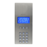
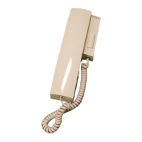
System Components and Available Versions
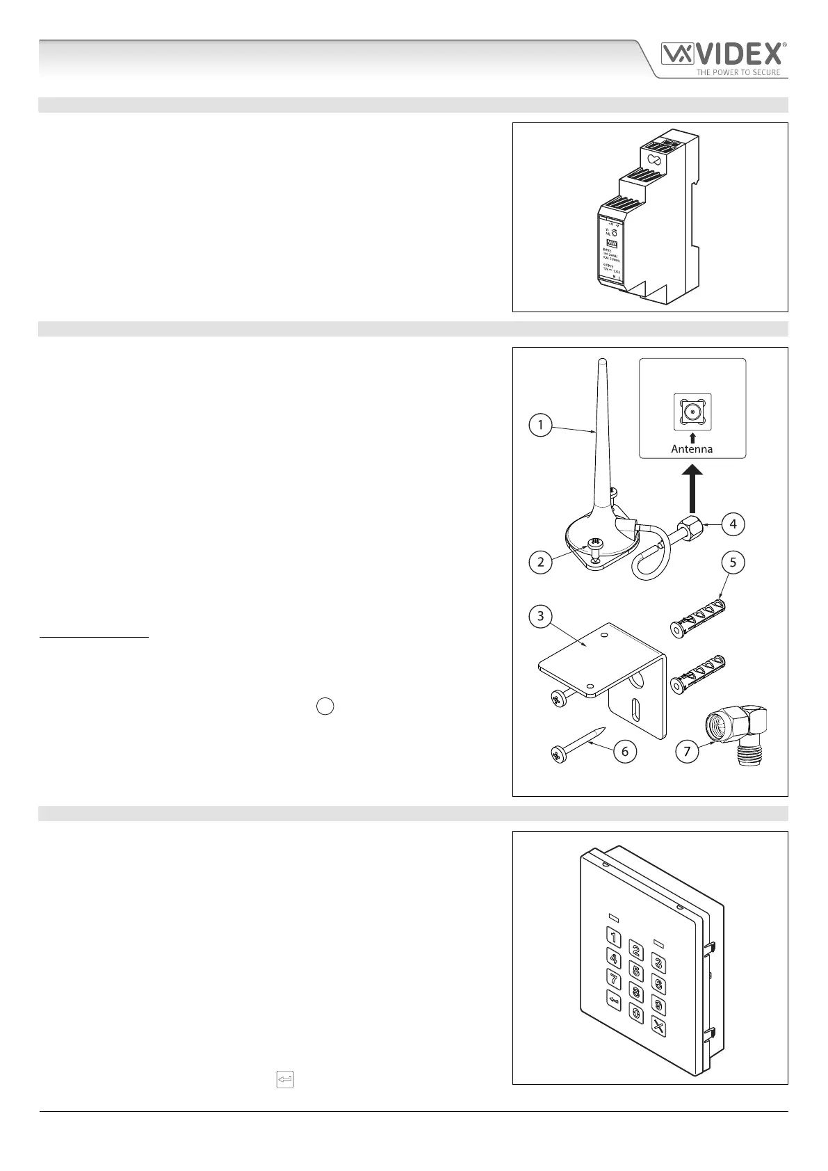
12VDC 2A POWER SUPPLY HDR1512
The Art. 4810 GSM PRO intercom is designed to work with power supplies in
the range of 12Vdc and should be capable of supplying a constant current of
no less than 1A. Both the GSM4K and GSM4KCR kits are supplied with a slim line
HDR-15-12, 12Vdc 1.25A power supply (refer to Fig.7).
Fig. 7
ART. 432 GSM ANTENNA
The Art.432 GSM antenna connects to the SMA female bulkhead connection on the
rear of the Art.4810 GSM PRO module. A GSM antenna with an SMA male connector
should be used (refer to Fig.8).
Antenna Parts
1. GSM antenna with magnetic base.
2. Self-threading screw (Ø3.5mm x 9.5mm).
3. Aluminium L bracket for mounting.
4. SMA male connector (cable length 2.5m).
5. Expansion type wall plugs (Ø6mm).
6. Self-threading screw (Ø4mm x 30mm).
7. Right angled SMA adapter.
IMPORTANT NOTE: An antenna must always be tted for the GSM module to
work. Always route the GSM antenna cable away from the microphone wires
and the power supply wires to avoid interference on the speech channels.
In instances where there is a tight tting space for the SMA male connector on
the antenna cable the right angled SMA adapter
can be used to help reroute
the cable down the back side of the GSM module.
Fig. 8
ART. 4903 CODELOCK
The Art.4903 codelock module (included as part of the GSM4KCR kits), see Fig.9,
can be powered from 12-24V AC or DC and includes 2 dry contact relay outputs
and two switched 0V push to exit inputs which can be used to trigger relay 1 &
2. It also includes an RS485 bus connection which can be linked to the Art.4810
GSM module and networked with other Art.4903 codelocks and/or Art.4850R
proximity devices (up to 8 devices in total).
When connected to the GSM PRO via RS485 it can operate up to 400 permanent
access codes (000-399) which can be assigned to trigger relay 1 or 2 or both. The
permanent codes can also have access levels and timebands assigned to them.
It can also operate up to 32 temporary codes. These codes can be between 4 - 8
digits long and are stored on the GSM PRO intercom. An additional two codes
(1 per relay) can be programmed directly via the keypad and are stored in the
codelock and not the GSM PRO module.
The relay time can be 01 - 99 seconds or set for latching (00). When in latching
mode, enter the code followed by ‘ENTER’
to latch and to unlatch the relay.
Fig. 9
SMA female bulkhead
connection on rear of
Art.4810 GSM PRO module

 Loading...