66250203 - V4.4 - 15/05/22
- 14 -
4000 Series Vandal Resistant Range
Art.4212 - Installation instructions
CONNECTION TERMINALS
12T +12Vdc Camera power supply unit
GNDV
Camera power supply ground & video ground
on coax video system
V2/V
Balanced video signal sync- (V2) or coax video
signal (V). Refer to “SWITHCES” table on this page
V1 Balanced video signal Sync+
PTE Push to exit button
TRD Trade signal (from Art.701T or other devices)
NO Relay out normally open contact
MAX 24Vac/dc
2A
C Relay out common contact
NC Relay out normally close contact
SL Accessory control signal
BS “Busy system” signal
L Bus connection - positive
− Bus connection - negative
+12 Power supply - positive
OC OUTPUT Open collector output
RS485 CONNECTION
TERMINALS
A
RS-485 serial inter-
face
B
GND Ground
WIEGAND CONNECTION
TERMINALS
D0 Data 0 output
D1 Data 1 output
LR
Red denied LED
status input
LG
Green accept LED
status input
TECHNICAL SPECIFICATION
Memory capacity: 998 users - 2800 keys - 2800 codes
Working voltage: 12 Vdc +/- 10%
Max absorb: about 350mA
Working Temperature: -20 +60 °C
CLEANING OF THE PLATE
Use a clean and soft cloth. Use moderate warm water or non-ag-
gressive cleansers.
Do not use:
• abrasive liquids;
• chlorine-based liquids;
• metal cleaning products.
Mounting with 4000 Series front support or surface unit
MANUAL REFERENCE
To install the panel with a 4000 Series front support Art.4852 or surface unit Art.4882, please refer to the 4000 Series
Mounting instructions provided with the front support or the surface unit or download it from this link:
http://www.videx-electronics.com/download/66848500.pdf
NOTES:
• This kind of installation is only available for these versions of
the panel:
Art.4212
Art.4212R
Art.4212V
Art.4212RV
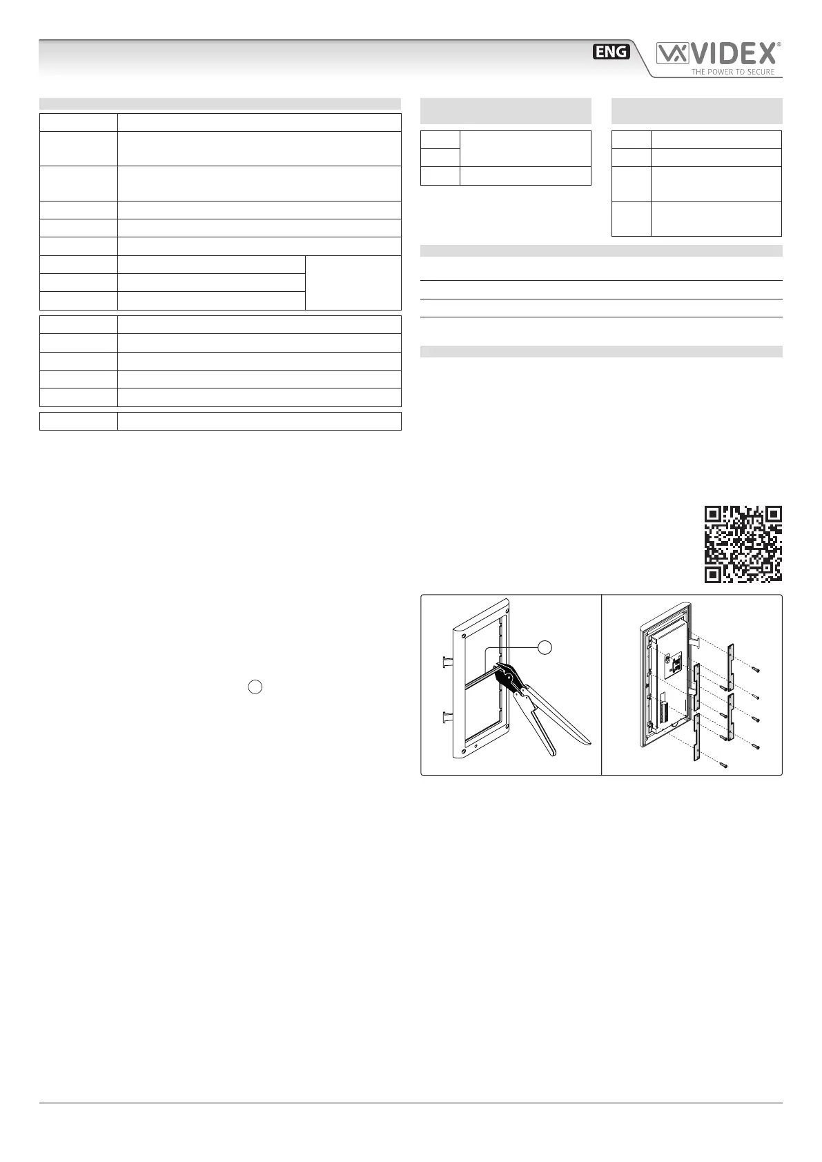
• In order to proceed with the panel installation with Art.4852
or Art.4882, remove the cross bar
A
from the support frame
as shown in Fig. 13.
• Fit the module xing brackets using the nxing screws as
shown in Fig. 14.
1 2
ON
Fig. 13 Fig. 14
Art.4212 Audio/video digital front panel Programming

 Loading...