66251750-EN - V1.0 - 05/06/17
40
4000 Series Vandal Resistant Digital GSM - Technical Manual
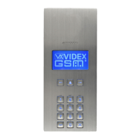
4000 Series Vandal Resistant Digital GSM Audio Intercom with Proximity
3.4 SPEECHBOARD VOLUME SB VOL
Selecting option 4 from the general settings menu will access the speechboard
volume control screen (refer to Fig.82). On this screen the speechboard volume of the
GSM panel can be adjusted. The current setting will be highlighted on the second line
of the screen (see Fig.82). The default speechboard volume level is set to 85 and can
be adjusted between 0 (low) up to 99 (high). Enter the volume level required then to
conrm and save the setting press the ENTER button and the screen will revert back to
the general settings menu (refer to Fig.78).
Fig. 82
3.5 SPEECHBOARD MODE SB MODE
Selecting option 5 from the general settings menu will access the speechboard mode
screen (refer to Fig.83. From this screen the speechboard mode can be set. The current
setting will be highlighted on the second line of the screen (see Fig.83). Three modes
are available: mode 1, 2 or 3 (see mode options below). The default setting is set to
mode 3. To set the speechboard mode select one of the following:
MODE 1 - Speechboard disabled - the speechboard will be switched OFF (no
speech annunciation will be heard through the panel’s speaker).
MODE 2 - Individual speech playback - the speechboard will be switched
ON. When an apartment is called the panel’s speechboard will playback the
individual numbers that make up an apartment number e.g. if calling apartment
25 the speech will playback “calling two ve”.
MODE 3 - Combined speech playback (default mode) - the speechboard will
be switched ON. When an apartment is called the panel’s speechboard will
playback the combined numbers that make up an apartment number e.g. if
calling apartment 36 the speech will playback “calling thirty six”.
Fig. 83
To conrm and save the setting press the ENTER button and the screen will revert back to the general settings menu (refer to Fig.78).
3.6 PROX BYTE SETTING PROX BYTES
Selecting option 6 from the general settings menu will access the proximity byte
setting screen (refer to Fig.84). From this screen the number of proximity bytes that
the onboard reader checks can be set. The current setting will be highlighted on the
second line of the screen (see Fig.84). There are three byte settings that the panel’s
reader can be set to check for: 2, 3 or 4 bytes (see byte settings below). The default
setting is set to check for 2 bytes. To set the number of bytes select one of the following:
2 Bytes (default setting) - set the panel to check for 2 bytes if the proximity fob/
card has no site code and only a 5 digit user code (955/T fobs or 955/C cards).
3 Bytes - set the panel to check for 3 bytes if the proximity fob/card has a 3 digit
site code and a 5 digit user code (PBX1E fobs or PBX2 cards).
4 Bytes - set the panel to check for 4 bytes for proximity fobs/cards that have a
longer site code and a 5 digit user code.
Fig. 84
To conrm and save the setting press the ENTER button and the screen will revert back to the general settings menu (refer to Fig.78).
to confirm
to cancel
SB VOL:(0-99)
85
to confirm
to cancel
SB MODE:(1-3)
3
to confirm
to cancel
PROX BYTES:(2-4)
2
Programming Screens