107
Note
For indoor units with 2 integrated heating/cooling cir-
cuits, heating/cooling circuit 2 is filled in the 1st step.
Then the filling of the rest of the system, including the
outdoor unit, is menu-guided. For this, the 4/3-way
valve switches in turn between each of the lines for the
heating/cooling circuit 1, DHW heating, defrost buffer,
etc.
Filling heating/cooling circuit 2
Note
Only for indoor units with 2 integral heating/cooling cir-
cuits
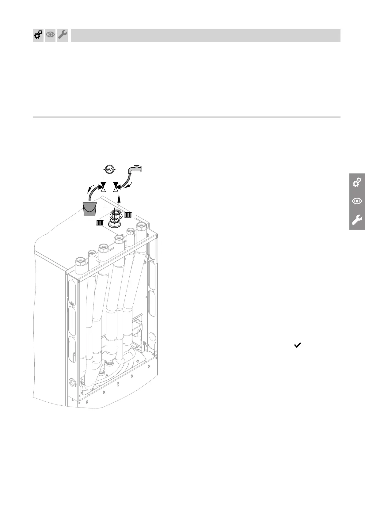
Fig. 74
1. Call up the filling function in the commissioning
assistant.
2. Connect the fill hose to the 3-way ball valve, heat-
ing/cooling circuit 2 flow.
3. Connect the drain hose to the 3-way ball valve,
heating/cooling circuit 2 return. Route the hose into
a suitable container or drain outlet.
4. Open the 3-way ball valves in the heating/cooling
circuit 2 flow and return as shown in Fig. 74.
Allow the heating water to flow in via the fill hose.
Required flow rate for filling with heating water:
■
Min. 600 l/h
■
Max. 1500 l/h
Filling pressure: 0.3 to 0.5 bar (30 to 50 kPa)
higher than diaphragm expansion vessel pre-
charge pressure
Factory-set pre-charge pressure of expansion ves-
sel: 0.75 bar (0.075 MPa) to 0.95 bar (0.095 MPa)
5. Start the filling process in the commissioning assis-
tant.
6. As soon as air bubbles are no longer coming out of
the drain hose, end the filling with .
The commissioning assistant switches to filling the
remaining consumer circuits.
7. Close both 3-way ball valves.
8. Remove the fill and drain hoses.
Commissioning, inspection, maintenance
Filling the system (cont.)
6222080