38
H
500
3000
450
200
1300
10
700
a
600
850
H
G
A
B
E
D
C
F F
L
K
N
600
r
M
940
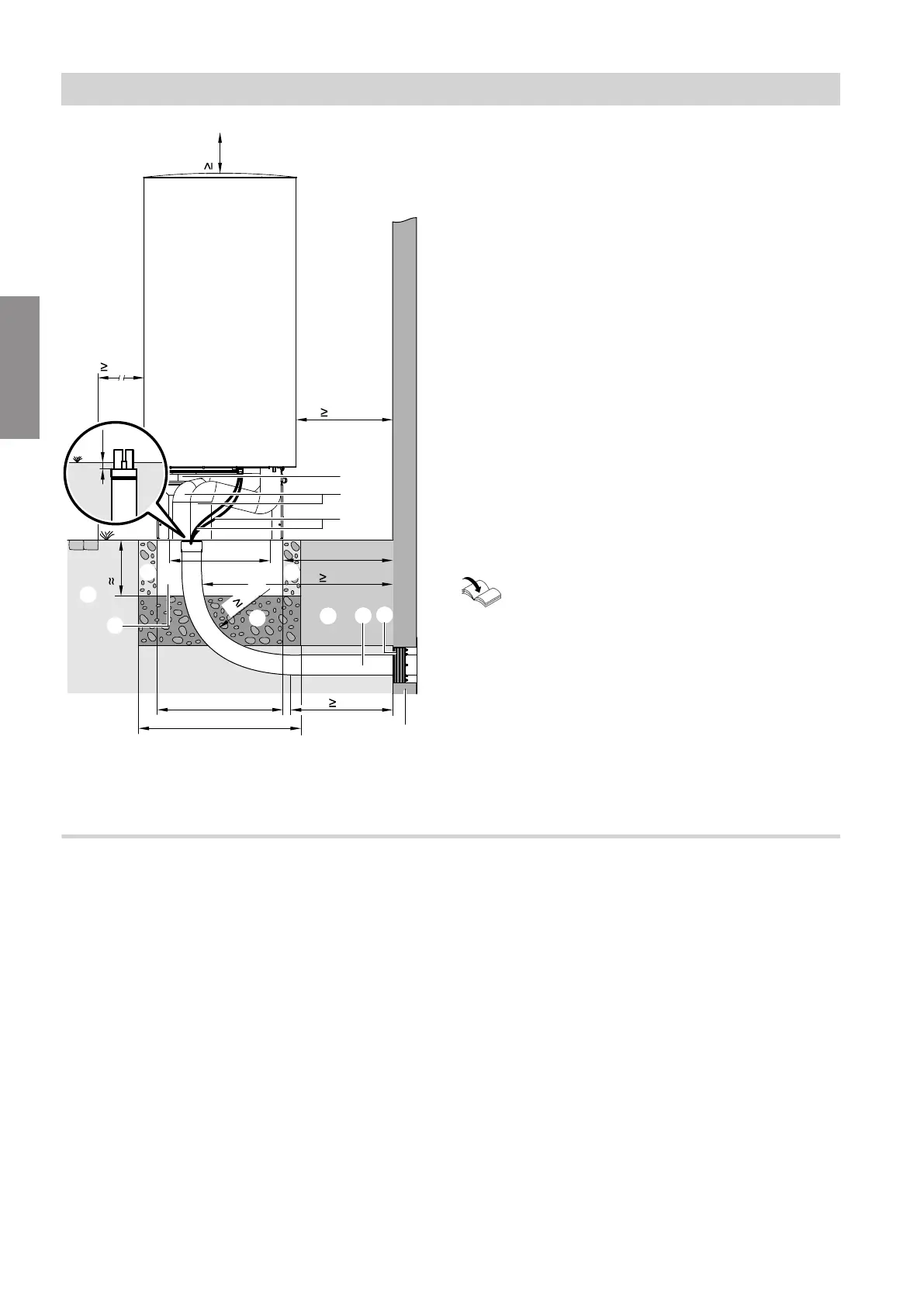
Fig. 22
A
Ground
B
Pathway, patio
C
Support for floorstanding installation (accessories)
D
Connection set, floorstanding installation (accesso-
ries)
E
Indoor/outdoor unit CAN bus communication cable
and outdoor unit power cable:
Route the cables free of strain.
F
For free drainage of condensate: Gravel bed as
soakaway
G
Ring seal (accessories)
H
Quattro connection line laid underground (acces-
sories)
K
Flexible separating layer between the foundations
and the wall
L
Frost protection for foundations (compacted
crushed stone, e.g. 0 to 32/56 mm); thickness of
layer subject to local requirements and building
regulations
M
Foundation strips
N
Wall
a Clearance between wall and foundation strip:
■
Types ...A04 to A13: ≥ 940 mm
■
Types ...A16 to A19: ≥ 980 mm
r Bending radius
Further installation instructions for the Quat-
tro connection line
Separate installation instructions
Note
■
Provide thermal insulation of sufficient thickness on
the pipework to the outdoor air: See table on
page 28.
■
Protect the pipework against damage. Avoid trip haz-
ards.
Line entry below ground level: Laying lines in a trench with a bend
Note
■
The following information for floorstanding installa-
tion applies to outdoor units with 1 or 2 fans. The
outdoor unit with 2 fans is shown as an example.
■
The following information applies to installation with
a support and an anti-vibration base. Installation with
a support is shown as an example.
Siting the outdoor unit
Floorstanding installation (cont.)
6222080
Installation