39
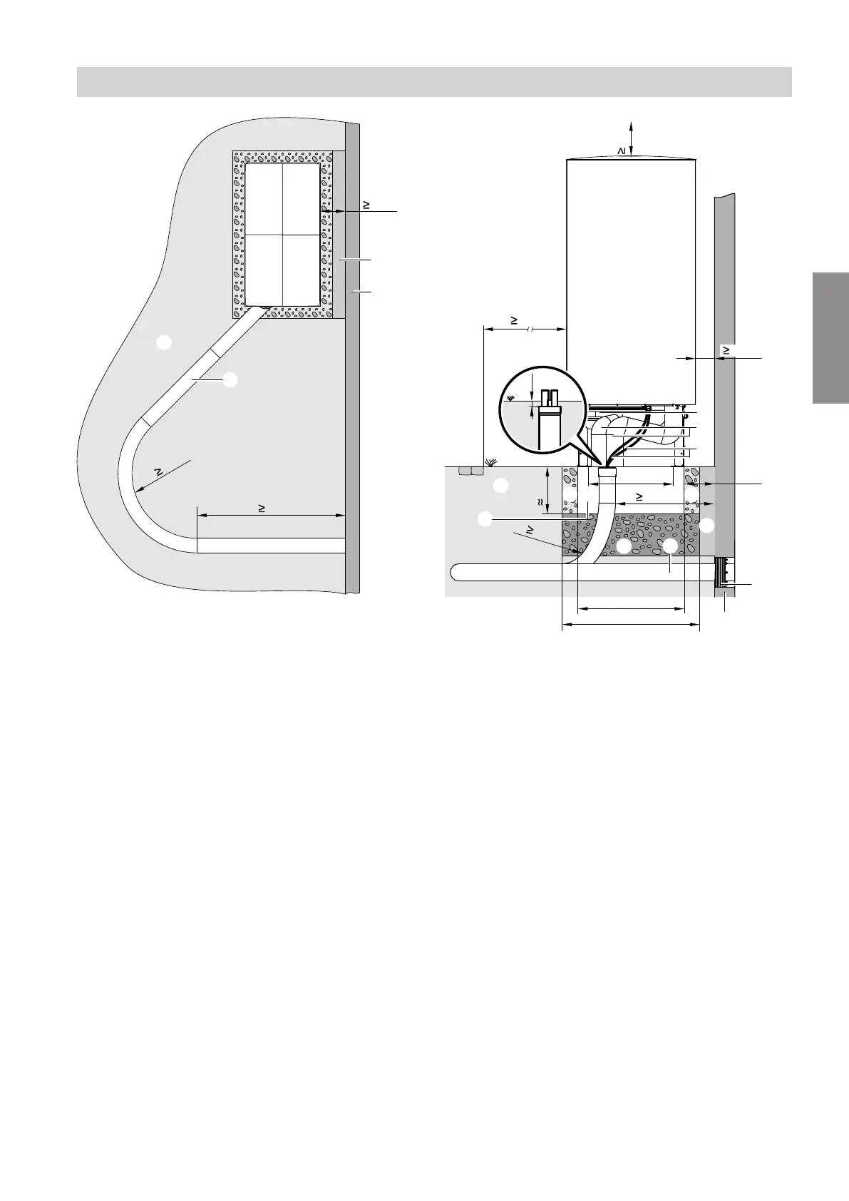
Fig. 23
10
G
A
500
3000
B
200
E
D
C
600
850
F
F
L
450
H
600
K
N
r
M
a
610
250
Fig. 24
A
Ground
B
Pathway, patio
C
Support for floorstanding installation (accessories)
D
Connection set, floorstanding installation (accesso-
ries)
E
Indoor/outdoor unit CAN bus communication cable
and outdoor unit power cable:
Route the cables free of strain.
F
For free drainage of condensate: Gravel bed as
soakaway
G
Ring seal (accessories)
H
Quattro connection line laid underground (acces-
sories)
K
Flexible separating layer between the foundations
and the wall
L
Frost protection for foundations (compacted
crushed stone, e.g. 0 to 32/56 mm); thickness of
layer subject to local requirements and building
regulations
M
Foundation strips
N
Wall
a Clearance between wall and foundation strip:
■
Types ...A04 to A13: ≥ 250 mm
■
Types ...A16 to A19: ≥ 290 mm
r Bending radius
Siting the outdoor unit
Floorstanding installation (cont.)
6222080
Installation