40
Further installation instructions for the Quat-
tro connection line
Separate installation instructions
Note
■
Provide thermal insulation of sufficient thickness on
the pipework to the outdoor air: See table on
page 28.
■
Protect the pipework against damage. Avoid trip haz-
ards.
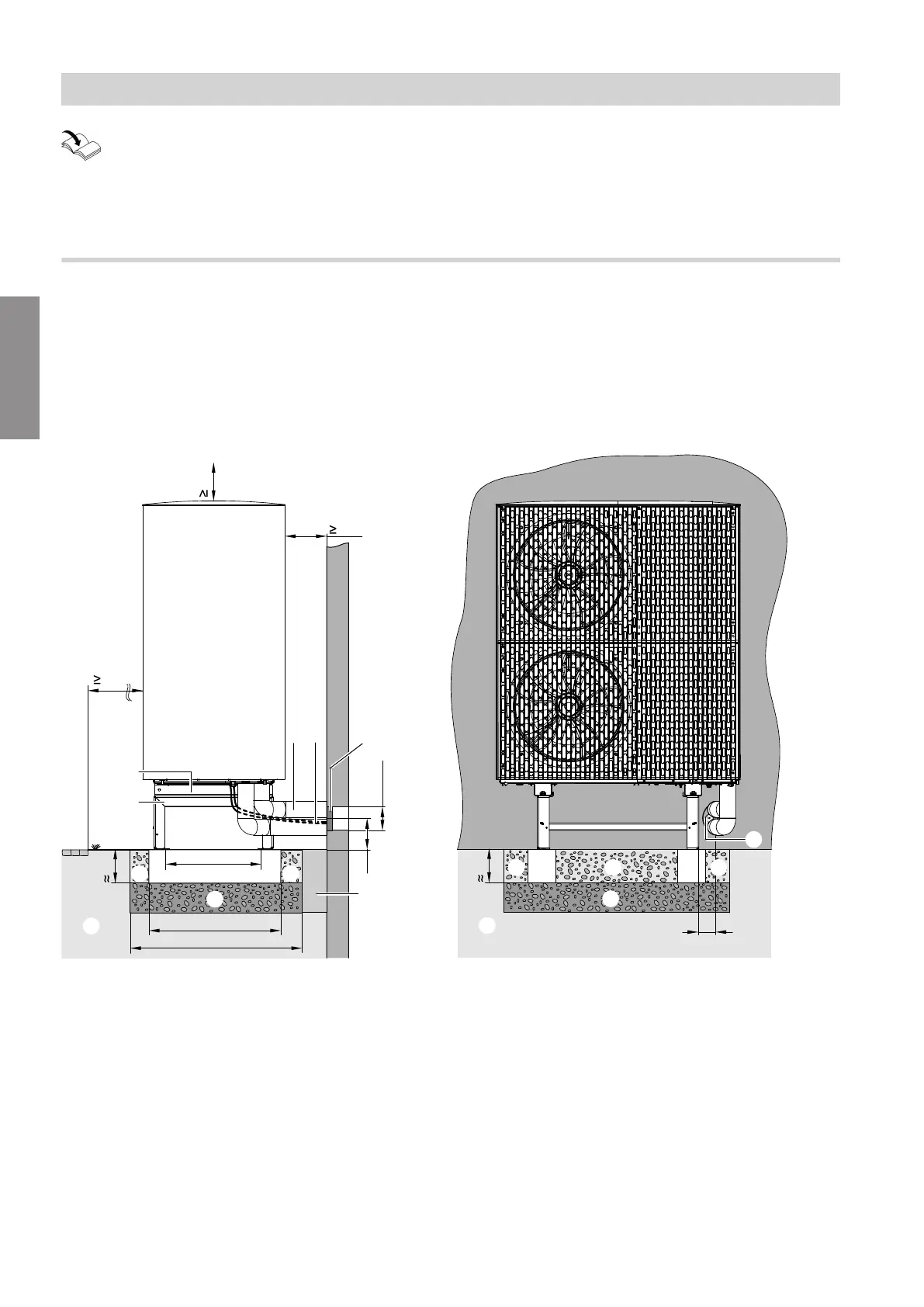
Line entry above ground level
Note
■
The following information for floorstanding installa-
tion applies to outdoor units with 1 or 2 fans. The
outdoor unit with 2 fans is shown as an example.
■
The following information applies to installation with
a support and an anti-vibration base. Installation with
a support is shown as an example.
3000
250
200
145
B
E
180
C
D
G
A
M
M
L
F
A
500
600
850
450
H
K K
500
H H
90
F
K K K
Fig. 25 Max. wall separation with design casing
(accessories): 300 mm
A
Ground
B
Pathway, patio
C
Hydraulic connection lines, indoor/outdoor unit
D
Indoor/outdoor unit CAN bus communication cable
and outdoor unit power cable:
Route the cables free of strain.
E
Condensate drain in the base plate:
Do not connect anything if the condensate can
drain freely.
F
Wall outlet (accessories) for electrical cables and
hydraulic lines
G
Support for floorstanding installation (accessories),
illustration without design casing (accessories)
H
Foundation strips
K
For free drainage of condensate: Gravel bed as
soakaway
L
Flexible separating layer between the foundations
and the building
M
Frost protection for foundations (compacted
crushed stone, e.g. 0 to 32/56 mm); thickness of
layer subject to local requirements and building
regulations
Siting the outdoor unit
Floorstanding installation (cont.)
6222080
Installation