53
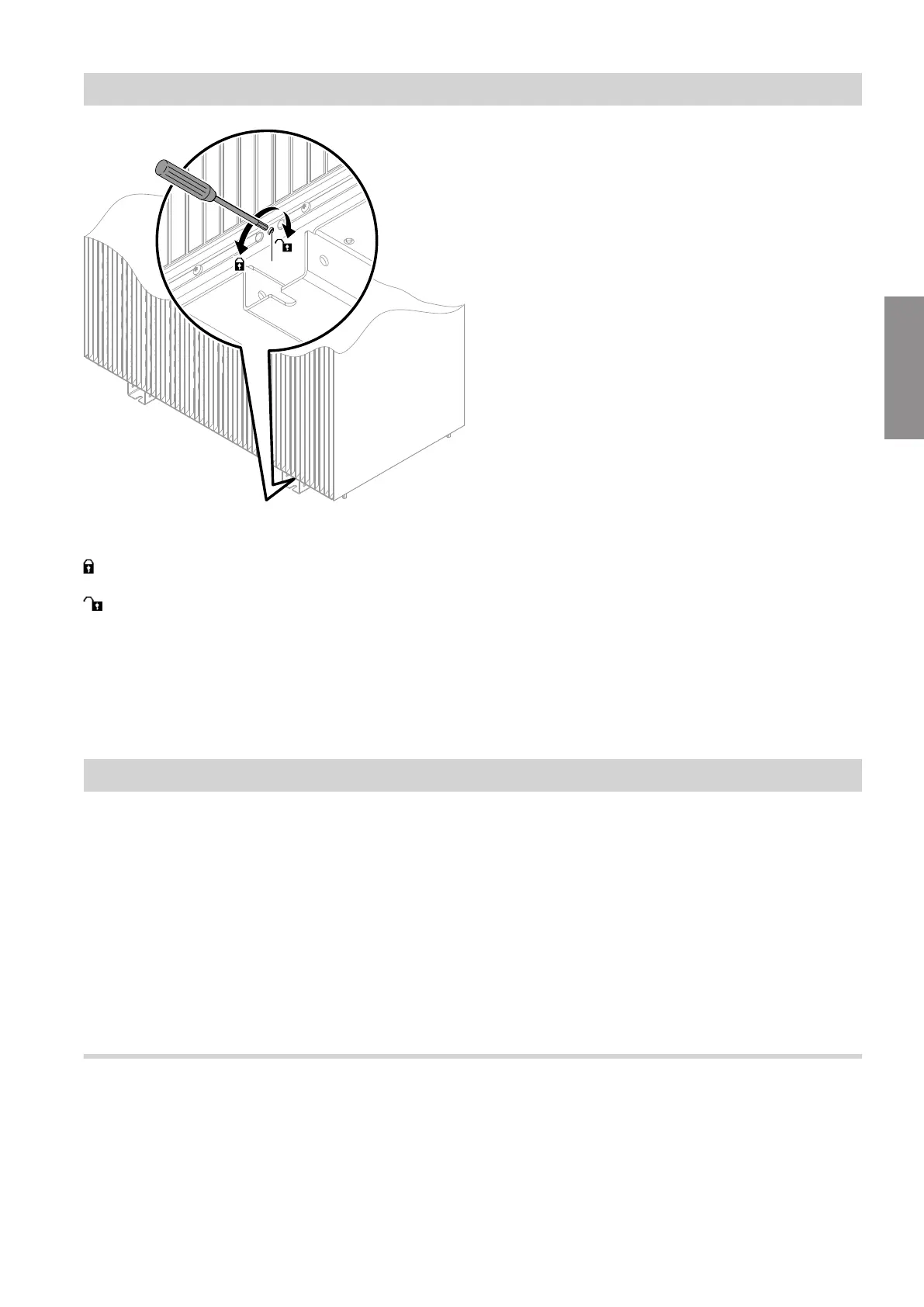
Fig. 38
A
Locking screw
Rotational direction for locking the transport
bracket
Rotational direction for releasing the transport
bracket
After positioning of the outdoor unit, check whether the
transport bracket is completely secured with an Allen
key (size 5).
Torque of the locking screw: Max. 4 Nm
Hydraulic connection of the indoor unit
Requirements for on-site connections
Observe the following requirements:
■
Components reflect current technology.
■
Components are approved for sealed unvented heat-
ing systems with operating pressures up to 3 bar.
■
Observe the manufacturer's instructions on installa-
tion.
Install an expansion vessel approved in accordance
with EN 13831 in the heating return of the heating sys-
tem.
Note
With underfloor heating circuits, always install a tem-
perature limiter to restrict the maximum temperature of
the underfloor heating.
Preparing the connections on the DHW side
For connecting the DHW side, observe EN 806,
DIN 1988, DIN 4753, TrinkwV Drinking Water Ordi-
nance [Germany] and DVGW (CH: SVGW regula-
tions). Observe other country-specific standards as
applicable.
Hydraulic connections
Hydraulic connection of the outdoor unit (cont.)
6222080
Installation