54
K
O
H
G F
L
O
F M N F K L
F
C
B
A
E
D
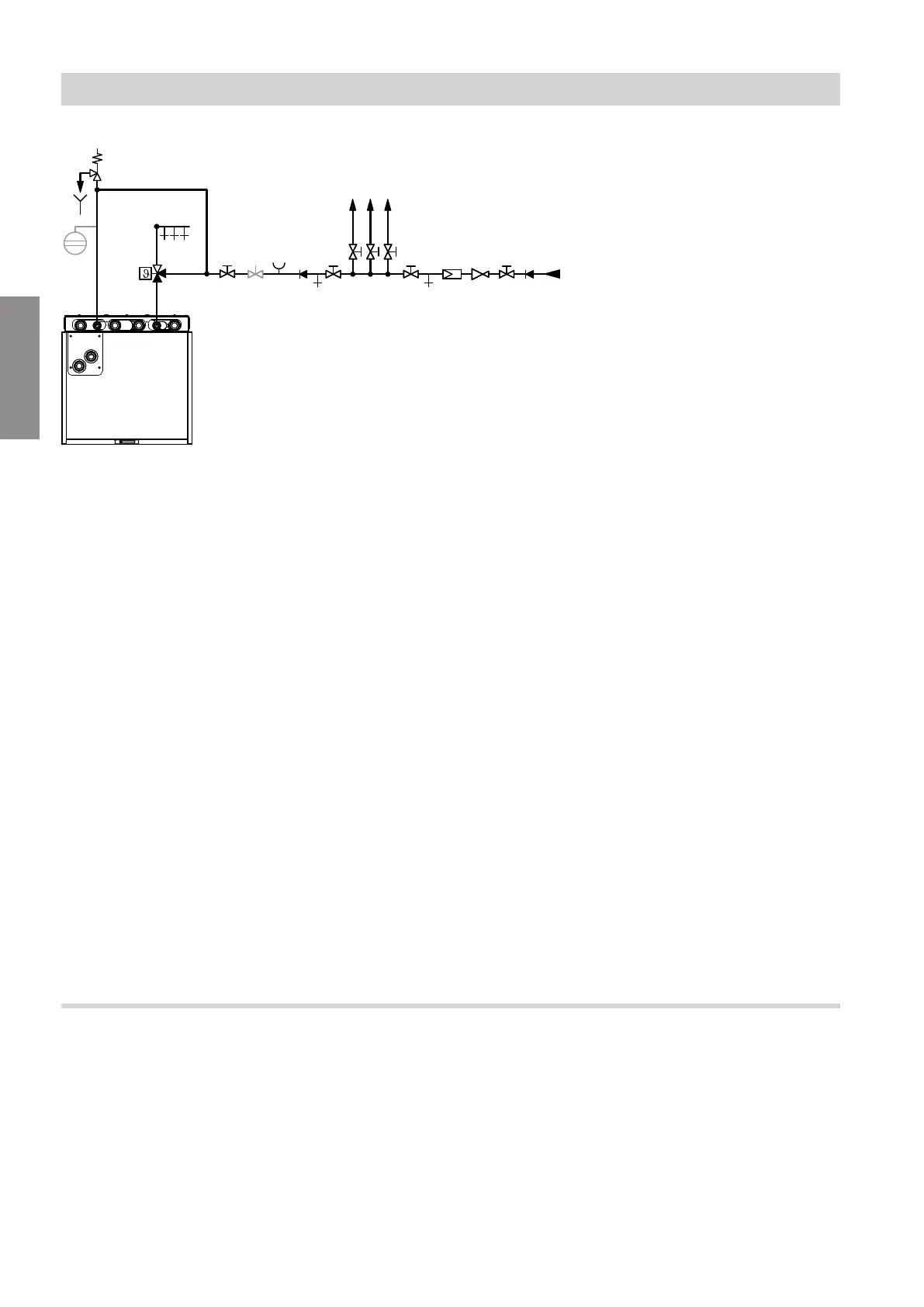
Fig. 39
A
Expansion vessel, suitable for drinking water
B
Visible discharge pipe outlet point
C
Safety valve
D
Automatic thermostatic mixing valve
E
DHW
F
Shut-off valve
G
Flow regulating valve
H
Pressure gauge connection
K
Non-return valve/pipe separator
L
Cold water
M
Drinking water filter
N
Pressure reducer to DIN 1988-200:2012-05
O
Drain valve
Safety valve
The DHW cylinder must have a safety valve to protect
against unduly high pressure.
Recommendation: Install safety valve above top edge
of cylinder. This means the DHW cylinder will not need
to be drained when working on the safety valve.
CH: According to W3 "Principles for creating potable
water installations", safety valves must be drained
directly via a visible unrestricted drain or via a short
outlet line to the drain network.
Drinking water filter
According to DIN 1988-2, a drinking water filter must
be installed in systems with metal pipework. Viess-
mann also recommends the installation of a drinking
water filter when using plastic pipes to DIN 1988 to
prevent contaminants entering the DHW system.
Automatic thermostatic mixing valve
With appliances that heat DHW to temperatures above
60 °C, an automatic thermostatic mixing valve must be
installed in the DHW line as protection against scald-
ing.
This also particularly applies when connecting solar
thermal systems.
Preparing the hydraulic connections
The following requirements must be met on site:
■
Components reflect current technology.
■
Components are approved in sealed unvented heat-
ing systems with operating pressures up to 3 bar.
■
Comply with manufacturer's instructions on installa-
tion.
Hydraulic connections
Hydraulic connection of the indoor unit (cont.)
6222080
Installation