55
Note
So that the system can be filled and flushed via the
commissioning assistant, fit a 3-way ball valve in each
of the following lines:
■
Flow and return lines for heating/cooling circuit 1/
external buffer cylinder and heating/cooling circuit 2
(if present)
■
Flow and return lines to the outdoor unit
If necessary, install 1 shut-off valve in the flow and one
in the return of the DHW cylinder.
Installing the hydraulic connection set (accesso-
ries)
"Hydraulic connection set" installation instruc-
tions
Grease with the valve grease supplied.
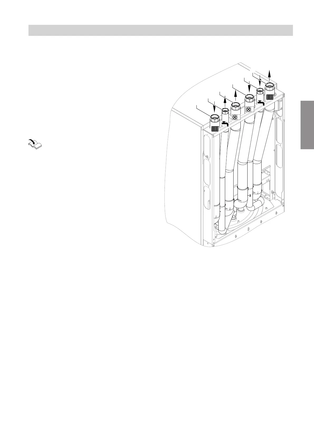
Note
The following diagram shows an example of the
hydraulic connection set for surface mounting with
upward connection.
Indoor unit with 1 integrated heating/cooling cir-
cuit
Fig. 40
A
Heating water return, heating/cooling circuit 1:
G 1¼ (female thread)
B
DHW: G ¾ (female thread)
C
Heating water to outdoor unit: G 1¼ (female
thread)
D
Heating water from outdoor unit: G 1¼ (female
thread)
E
Cold water: G ¾ (female thread)
F
Heating water flow, heating/cooling circuit 1: G 1¼
(female thread)
Hydraulic connections
Hydraulic connection of the indoor unit (cont.)
6222080
Installation