56
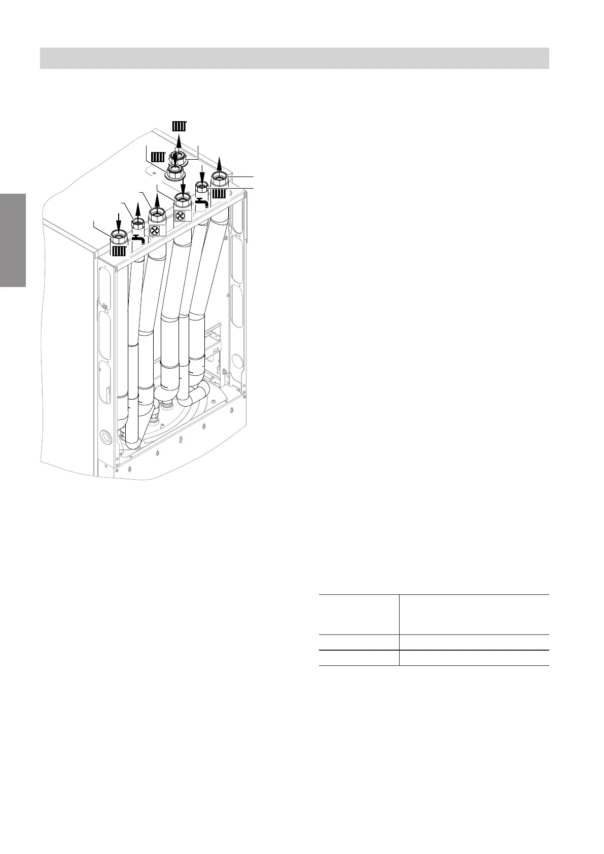
Indoor unit with 2 integrated heating/cooling cir-
cuits
Fig. 41
A
Heating water return, heating/cooling circuit 1:
G 1¼ (female thread)
B
DHW: G ¾ (female thread)
C
Heating water to outdoor unit: G 1¼ (female
thread)
D
Heating water from outdoor unit: G 1¼ (female
thread)
E
Cold water: G ¾ (female thread)
F
Heating water flow, heating/cooling circuit 1: G 1¼
(female thread)
G
Heating water return, heating/cooling circuit 2:
G 1¼ (female thread)
H
Heating water flow, heating/cooling circuit 2: G 1¼
(female thread)
Hydraulic connections
1. If the expansion vessel fitted in the indoor unit is
insufficient, equip the secondary circuit on site with
an additional expansion vessel.
2. Connect all secondary side hydraulic lines (room
heating/cooling, DHW heating) to the indoor unit.
!
Please note
Hydraulic connections subjected to mechani-
cal loads lead to leaks, vibrations and appli-
ance damage.
Connect on-site lines so that they are free of
load and torque stress.
Note
Recommendation: Install a suitable heating water
filter in the secondary circuit to remove magnetic
and non-magnetic dirt particles, e.g. the heating fil-
ter with magnetite separation (accessories).
!
Please note
Contamination in the secondary circuit will
lead to blockage of the hot water filter in the
outdoor unit.
Before making the hydraulic connection of
the indoor and outdoor unit, thoroughly flush
the secondary circuit.
3. Grease and connect the hydraulic connection lines
to the outdoor unit e.g. hydraulic connection set
(accessory).
4. Recommendation: Check for leaks with nitrogen.
5.
!
Please note
Leaking hydraulic lines and joints will cause
damage to the system or to the building.
Do not thermally insulate joints until after
completion of the leak test following filling:
See chapter "Building up the system pres-
sure".
Thermally insulate pipework inside the building. If
room cooling is planned for the building, use ther-
mal and vapour diffusion-proof insulation.
Pipework inter-
nal
7
Min. thickness of thermal in-
sulation layer with
λ = 0.035 W/(m·K)
≤ 22 mm 20 mm
> 22 mm 30 mm
λ Thermal conductivity
Hydraulic connections
Hydraulic connection of the indoor unit (cont.)
6222080
Installation