7
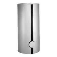
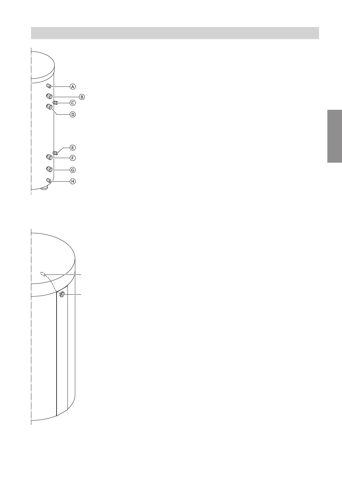
Fig. 2 Back
A
Air vent valve (EL)
B
Heating water flow 1 (HV1)
to the heating circuits
C
Sensor well 1 (SPR1)
for cylinder temperature sensor
D
Heating water flow 2 (HV2)
from the heat source
E
Sensor well 2 (SPR2)
for cylinder temperature sensor
F
Heating water return 2 (HR2)
from the heating circuits
G
Heating water return 1 (HR1)
to the heat source
H
Drain outlet (E)
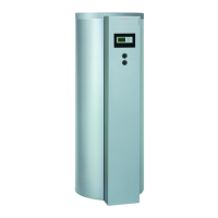
Type SVP (400 l capacity)
Fig. 3 Front
A
Thermometer sensor retainer
B
Thermometer (TH)
Installation information
Product information (cont.)
5517 175 GB
Installation
 Loading...