Connections
19
Safety Connections and Pressure Testing
Installation Instructions
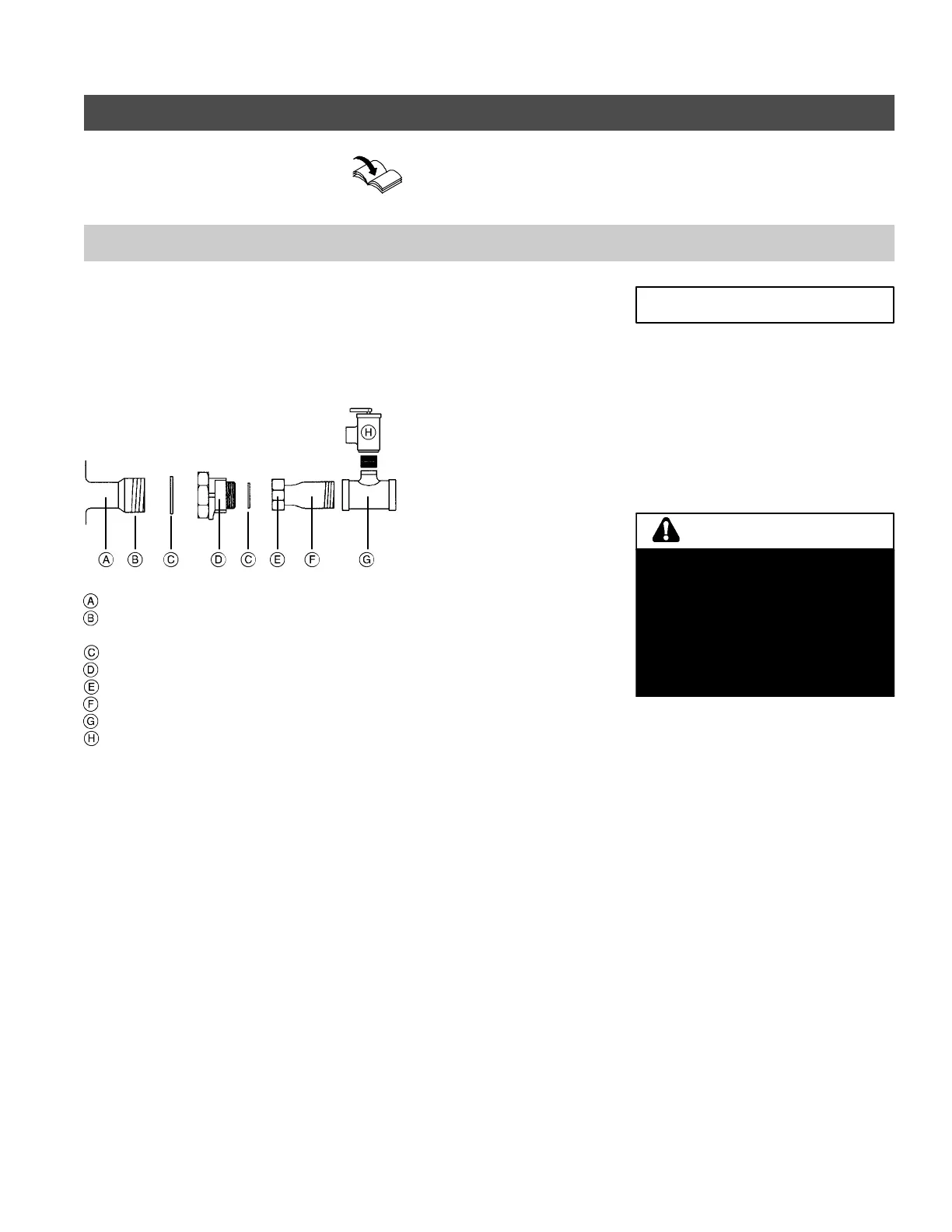
Viessmann Safety H eader
(Accessory)
Install safety devices on the boiler
Boiler water supply connection
Welded boiler nipple
(non-NPT connection)
Gasket
Reducer, 2” x 1
1
/
2
“
Union, 1
1
/
2
“
NPT adaptor, 1
1
/
2
“
Tee, 1
1
/
2
x1
1
/
2
x
3
/
4
”
Pressure relief v alve
Install safety devices.
1. Install pressure relief valve. Pipe
pressure relief valve as illustrated if
not installing a Vies smann Safety
Header (Accessory).
2. Install discharge pipe on pressure
relief valve. The discharge pipe
should terminate approximately 6” /
150 mm above a floor drain. The end
ofthepipemustnot be threaded.
Minimum connection diameters:
Pressure relief v alve
3
/
4
“..........................
Discharge pipe
3
/
4
“.....................................
Piping to precharged
expansion tank
3
/
4
“...................................
This boiler does not require a flow
switch.
Install the (approved) factory supplied
pressure relief valve .
Removal of air from the system must
occur via use of air vent(s) in the
system supply. To ensure the boiler can
be purged of all air, ensure
supply/return water lines do not contain
restrictive piping where air could be
trapped.
5285 838 v2.1
IMPORTANT
Do not install an isolation valve
between boiler and pressure relief
valve.
The discharge pipe for the pressure
relief valve must be oriented to
prevent scalding of attendants.
Pipe pressure relief valve discharge
pipe close to floor drain. Never pipe
discharge pipe to the outdoors.
WARNING