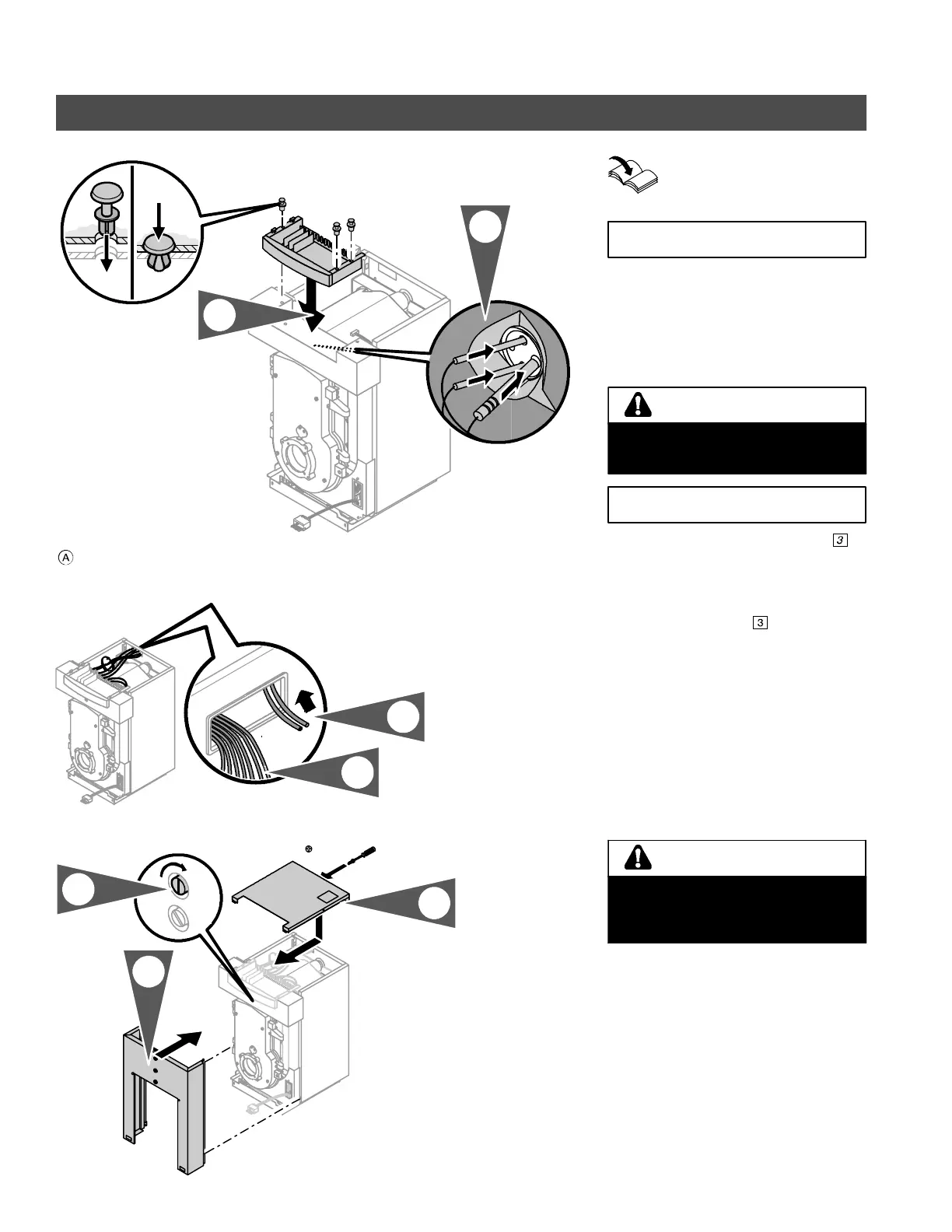
Connections
26
Electrical Connections
Installation Instructions
Boiler Control (for all
connections to control base)
The power supply cable is shipped with
the boiler control.
1. Insert control base into upper front
panel. Fasten with supplied rivets
(shipped with boiler control).
Boiler temperature sensor number
is
shipped with the boiler control (does not
apply to Vitotronic 100, KK5 and KK10).
2. Carefully push high limits and boiler
temperature sensor
behind front
panel and into sensor wells as far as
possible. Lay ex cess sensor cabling
and capillary tubing on insulation.
3. Channel power supply cable or
Power/Pump Module cable (for
Vitotronic 200) and all other
120 VAC cabling toward boiler
control.
4. Channel low voltage cables (i.e.
sensor cables) through cable opening
toward boiler control.
5. Attach top panel with supplied sheet
metal screws as shown.
6. Attach front cover panel to boiler.
7. Lock front cover panel in place by
turning locking screw clockwise.
5285 838 v2.1
2.
1.
Cover panel, if supplied
3.
4.
3.9 x 9.5
closed
open
5.
6.
7.
IMPORTANT
Do not kink capillaries. Proper
operation of sensors is not possible if
capillaries are kinked.
WARNING
IMPORTANT
Always route all cables and capillaries
between nylon backed insulation and
metal enclosure panels, never directly
on cast-iron heat exchanger.
CAUTION