Service Diagnostics and Procedures-Disassembly
© 2010 Viking Preferred Service 46
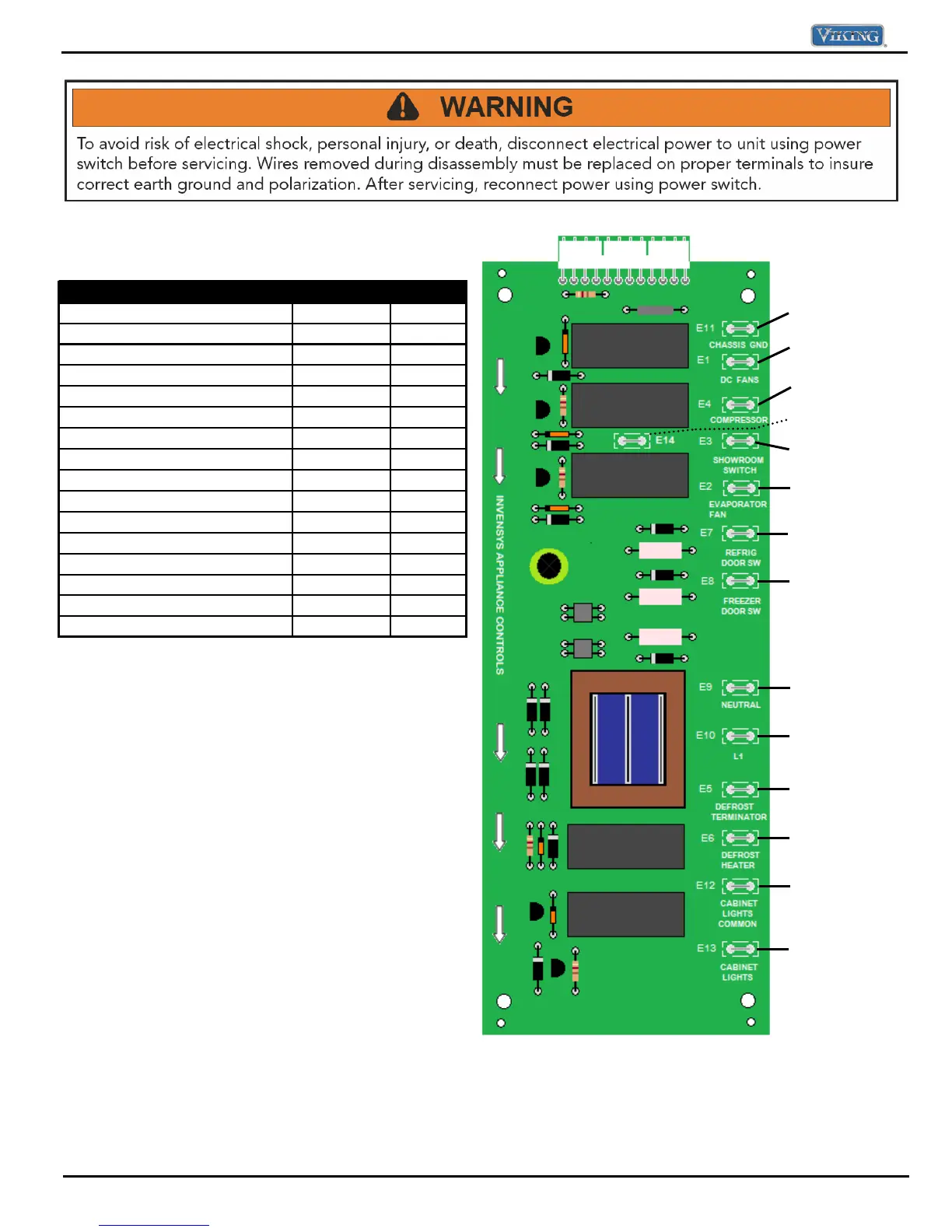
Component Testing---High Voltage Board
NOTE:
On models built after 5/19/2010, the built in pocket heater
is connected to E14. When the Compressor/Condenser
relay is de-energized, 115 Volts is supplied to Terminal 14.
E14 is wired to the N.C contact in the relay. When the
Relay is energized; power is removed from the heater.
E11
r
n
E1 Refrigerator /
Condensate Fans
E4 Compressor
E3 Line In-115 VAC
E14 Pocket heater
E2 Evaporator fan
E7 Fresh F door SW
E8 Freezer door SW
E9 Neutral
E10 Line in –115 VAC
E5 Defrost Terminator
E6 Defrost Heater
E12 Neutral In
E12 Light relay
High Voltage Board
Component Test Point Reading
Refrigerator/Condensate Fans E1 - E11 24 VDC
Evaporator Fans E2 - E9 115 VAC
L1 E3 - E9 115 VAC
Compressor/Condensor Fan E4 - E9 115 VAC
Defrost Terminator (Open) E5 - E9 0 VAC
Defrost Terminator (Closed) E5 - E9 115 VAC
Defrost Heater - Out E6 - E9 115 VAC
Ref Door Switch E7 - E9 115 VAC
Freezer Door Switch E8 - E9 115 VAC
Neutral In E9 - E10 115 VAC
Line In E10 - E9 115 VAC
Ground E11 N/A
Neutral in - Lights E12 - E10 115 VAC
Neutral out - Lights E13 - E10 115 VAC
Pocket heater (See Note below)
E14 - E9 115 VAC