© 2010 Viking Preferred Service
72
Service Diagnostics and Procedures
Ice Dispenser Module Assembly
When the ice dispenser Ice Door switch is activated,
120 volts is sent to the relay coil and the Ice Door
motor is energized. After the switch is deactivated,
the holding relay will keep the Ice Door open for
an additional 8 seconds to allow any remaining ice
cubes in the chute to dispense.
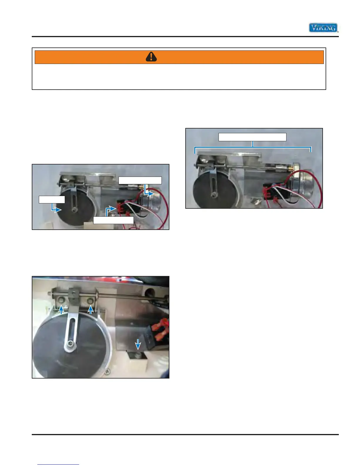
1. Remove cavity cover (follow cavity cover
disassembly procedure).
2 Remove screws to remove Ice Module
Assembly.
3. Replace ice dispenser assembly if necessary.
4. Reverse procedure to reinstall.
WARNING
To avoid risk of electrical shock, personal injury, or death, disconnect electrical power to unit using power
switch before servicing. Wires removed during disassembly must be replaced on proper terminals to insure
correct earth ground and polarization. After servicing, reconnect power using power switch.
Ice Dispenser Assembly
Ice Door Motor
Ice Door
Holding Relay