Service Diagnostics and Procedures
© 2010 Viking Preferred Service 84
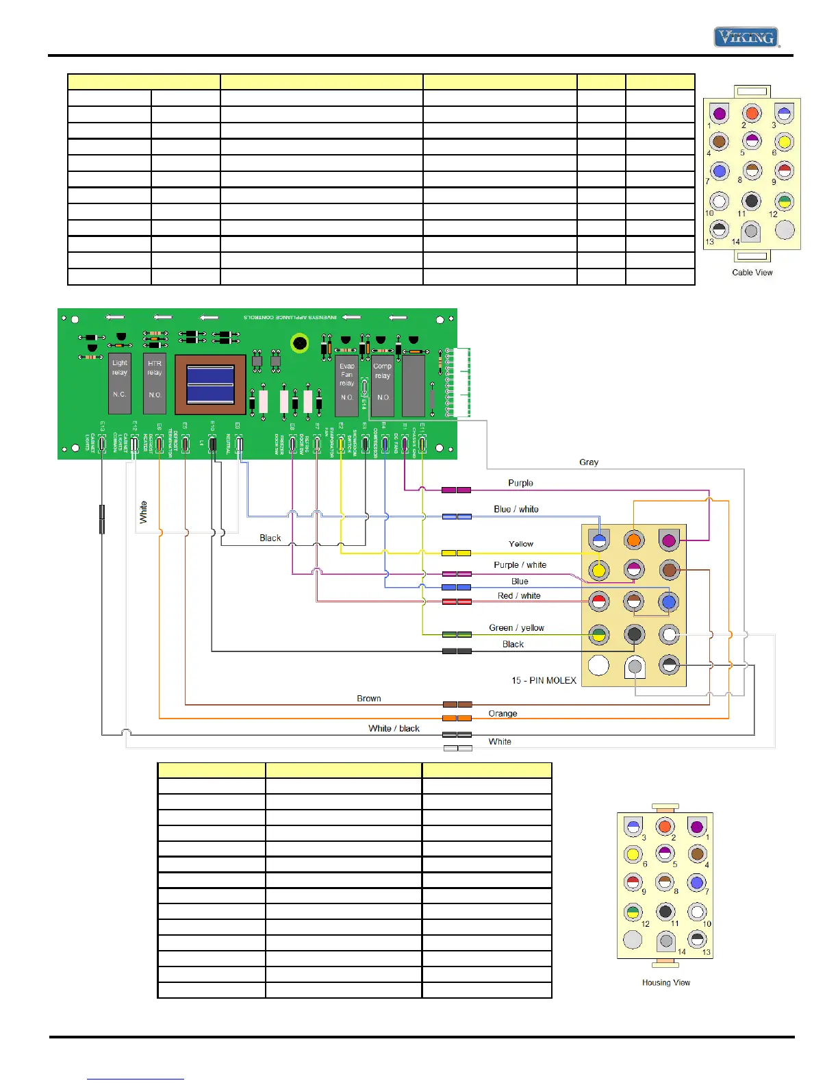
Terminal to Terminal
Description Wire Colors Ω - V Volts
1
12 Fresh Food Fan only Purple to Green w/ Yellow 3.2 mΩ 24 VDC
1
12 Fresh Food Fan AND Service Fan Purple to Green w/Yelllow 1.6 mΩ 24 VDC
2
3 Defrost Heater Orange to Blue w/White 30.3 Ω 115 VAC
6
10 Freezer Fan -120 VAC Yellow to White 28.0 Ω 115 VAC
4
11 Defrost Bimetal Brown to Black 0 or ∞ 0 or 115 V
5
11 Freezer door switch Purple w/White to Black 0 or ∞ 0 or 115 V
7
10 Line out to Inverter board Blue to White 2 mΩ 115 VAC
8
10 Line out to Condenser fan motor Brown w/white to White 550 Ω 115 VAC
9
11 Refrigerator door switch Red w/White to Black 0 or ∞ 115 VAC
11
10 Main in to HV Board Black to White N/A 115 VAC
13
*
Neutral OUT to cavity lights White w/Black N/A N/A
14 (See note)
9 Power out to pocket heater Gray N/A 0 or 115 V
Chart for cable view layout
Note: E14 was added on
units produced after
5/19/2010. Circuit is for
factory installed pocket
heater.
Molex Connection
Wire Colors
HV Board connection
1
Purple
E1
2
Orange
E6
3
Bl
ue w/White tracer
E9
4
Brow
n
E5
5
Purple w/White tracer
E8
6
Ye
llow
E2
7
Blue
E4
8
Brown w/White tracer
E4
9
Red w/White tracer
E1
10
Whi
te
E12
11
Black
E10
12
Green w/Yellow tracer
E11
13
W
i
th w/Black tracer
E13
14 (See not
e)
Gray
E14