© 2009 Viking Preferred Service
26
Service Diagnostics and Procedures
Control Board Diagnostics (continued)
Convection Fan
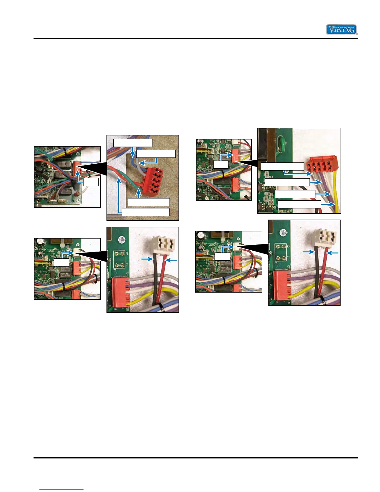
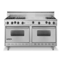
Locate the P4 connector and P1 connector on the
main control board. The P4 connector will have a
molex plug containing a green, orange, grey, and
blue wire. The green wire goes to the hi speed
winding of the fan, the orange wire goes to the low
speed winding of the fan, the grey wire goes to the
reverse direction of the fan and the blue wire goes
to the forward direction of the fan.
With the molex plug removed from the P4
connector, use an Ohm meter to measure resistance
between the grey wire in the molex connector
and the black wire of the P1 connector (reverse
direction) or blue wire in molex connector and
black wire of the P1 connector (forward direction).
The resistance should be approximately 100 Ω. If
no resistance is read, remove the fan to repair or
replace as shown on page 33.
Door Lock Motor
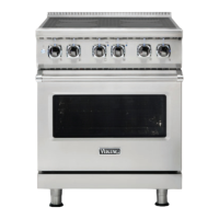
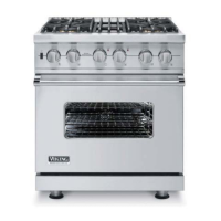
Locate the P12 connector and P1 connector on the
main control board. The P12 connector will have a
molex plug containing a grey, purple, white, yellow
wire. The grey wire goes to the cycle light, the
purple wire goes to the clean light, the white wire
does to the door lock motor, and the yellow wire
goes to the oven light.
With the molex plug removed for the P12
connector, use an Ohm meter to measure resistance
between the white wire in the molex connector
and the black wire at the P1 connector. Resistance
should be approximately 12.1 K
Ω. If no resistance
is read, remove the door lock motor to repair or
replace as shown on page 35.
P-4
Forward Fan
Reverse Fan
Hi Speed Fan
Low Speed Fan
P-3
P-3
P-1
To Cycle Light
To Clean Light
To Door Lock
To Oven Light


 To Next Page