© 2009 Viking Preferred Service
41
Induction Switch
The purpose of the surface switch is to control the
cooking operation. Once the end user chooses a
setting, the corresponding amount of power and
cycle rate to deliver a given output is sent to the
interface board. The interface board communicates
between the indicator and the generator. The
indicator communicates if a pot is in place. The
generator receives input to power the inductor and
deliver the desired output.
To access the surface switch, see Conrol Panel
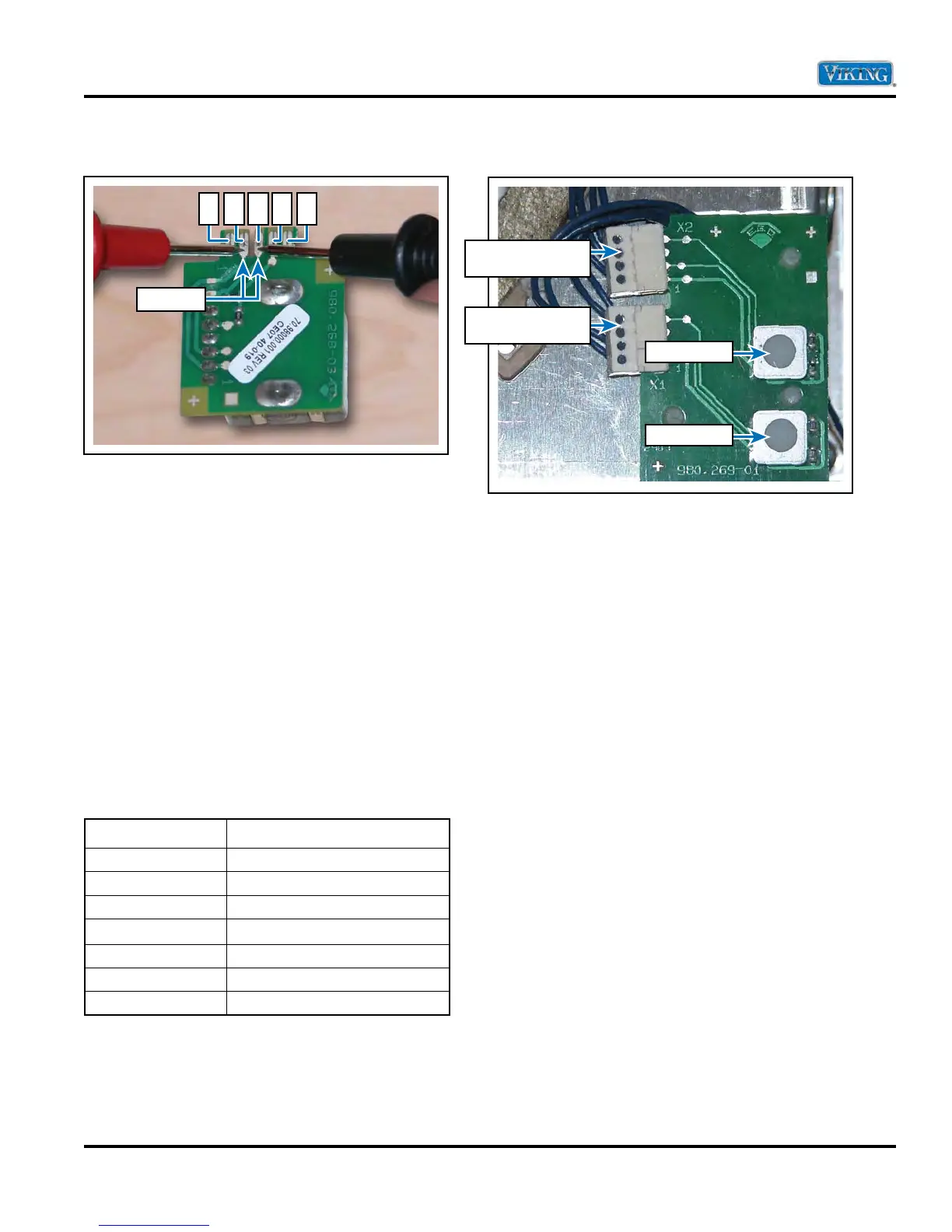
Removal (page 23). The switch is a 10K potentio-
meter. Measure the resistance at different switch
settings. If no reading or an open occurs the switch
is bad. See chart below for resistance readings:
Induction Switch Resistance Chart
Setting Resistance
Off
11690 Ω +/- 50 Ω
Simmer
9430 Ω +/- 50 Ω
Low
9003 Ω +/- 50 Ω
Medium-Low
7850 Ω +/- 50 Ω
Medium
6600 Ω +/- 50 Ω
Medium-High
2840 Ω +/- 50 Ω
High
9.6 Ω +/- 50 Ω
Measured from positions 2 and 3
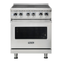
Indicator
The indicator serves as a means to ensure a pot is
on the cooking surface. The indicator will flash if no
pot is recognized or if an error is present.
LED flashes with pan detection and residual heat.
When cook top is off and residual heat is present,
the zone indicator flashes. In case of oveheat
powerbaord LED’s flash rapidly.
The indicator receives a signal from the interface
indicating which inductor is to be energized. The
indicator monitors this signal and will flash if no pot
is recognized or will display an error message if a
error is present (refer to error chart page 16). Verify
wire connections are tight, and ohm wires end to
end. If continuity is present, check the induction
switch and interface. If both are OK, replace the
indicator.
Note: Left and right module interface board
connection CANNOT be reversed. If this occurs
error code ER31 will occur.
Service Diagnostics and Procedures
2 3 4 51
Test Points
Input from Interface/
Induction Adapter
Input from Interface/
Induction Adapter
LED indicator
LED indicator


 To Next Page