EasyManua.ls Logo

Viking VDSC536 User Manual

Viking VDSC536
53 pages
To Next Page IconTo Next Page
Page #1 background imageLoading...
Page #1 background image
Service
Manual
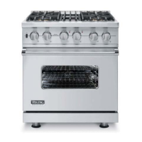
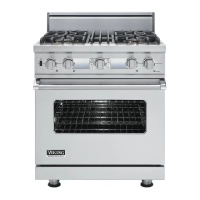
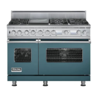
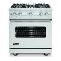
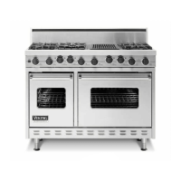
30, 36, & 48 Inch
Dual Fuel Range
Preferred Service
VDSC530
VDSC536
VDSC548
SMC-0003B
December 2009
®
This manual is to be used by quali ed appliance technicians only. Viking
does not assume any responsibility for property damage or personal
injury for improper service procedures done by an unquali ed person.
This Base Manual covers general and
speci c information including, but not
limited to the following models:

Table of Contents

Other manuals for Viking VDSC536

Questions and Answers:

Viking VDSC536 Specifications

General IconGeneral
Width36 inches
Oven Capacity5.0 cu. ft.
Number of Burners6
ConvectionYes
FinishStainless Steel
MaterialStainless Steel
Dimensions (WxDxH)36 x 28 x 36 inches
TypeFreestanding
Ignition TypeElectronic
Gas TypeNatural Gas or LP
Burners6 sealed burners

Summary

Service Manual

30, 36, & 48 Inch Dual Fuel Range

Covers general and specific information for Viking Dual Fuel Ranges.

Important Information

Safety Information

Explains safety alert symbols and hazard definitions for user safety.

Warranty Details

Details the warranty coverage for Viking Professional Series Dual Fuel Ranges.

General Information

Appliance Specifications

Technical specifications including ratings, clearances, and dimensions.

Electrical and Gas Requirements

Specifications for electrical and gas connections.

Performance Checklist

Checks to be performed by an installer after installation.

Troubleshooting

Error Codes and DSI Board Faults

Explains LED error codes and DSI board fault codes for diagnostics.

Oven Component Troubleshooting

Troubleshooting common oven component failures with corrective actions.

Element Operation Checks

Step-by-step guides for checking convection, bake, and broil element operation.

Griddle and Spark Module Testing

Diagnostic steps for griddle operation and spark module testing.

RTD Characteristics and Testing

Information on RTD sensor testing and specifications.

Disassembly Procedures

Control Board Access and Removal

Steps to access and remove the main control board assembly.

Door Assembly and Related Components

Procedures for removing door assembly, gasket, handle, and glass.

Hinge and Sensor Removal

Procedures for removing door hinges and the oven temperature sensor.

Bake Element and Rack Support Removal

Procedures for removing the bake element and rack supports.

Convection Fan Assembly Removal

Steps to remove the convection fan cover and assembly.

Heating Elements and Control Panel Removal

Procedures for removing bake/broil elements and control panel.

Thermostat and Selector Removal

Procedures for removing oven thermostat and function selector.

Oven Light and Switch Removal

Procedures for removing oven light bulb and switch.

Indicator Lights and Door Lock Removal

Procedures for removing indicator lights and door lock assembly.

IRIS Module and Griddle Component Removal

Procedures for removing IRIS module and griddle components.

Spark Module and Burner Valve Removal

Procedures for removing direct spark module and burner valve.

Trim and Backguard Removal

Procedures for removing island trim and backguard assembly.

Main Top and Jet Holder Removal

Procedures for removing the main top and jet holder.

Manifold and Pressure Regulator Removal

Procedures for removing manifold assembly and pressure regulator.

Burner Base and Side Panel Removal

Procedures for removing burner base assembly and side panels.

Blower Motor and Back Panel Removal

Procedures for removing blower motor and back panel.

Terminal Block Removal

Procedure for removing the terminal block.

Wiring Diagrams

Oven Control Board Schematic

Detailed wiring diagram of the oven control board.

Heating Element Strip Circuits

Wiring diagrams for specific heating elements.

Motor Wiring Diagrams

Wiring diagrams for convection, blower, and door latch motors.

Electronic Thermostat and Griddle Systems

Wiring diagrams for electronic thermostat and griddle systems.

Model-Specific Wiring Diagrams

Wiring diagrams for VDSC530, VDSC536, and VDSC548 Dual Fuel Ranges.

Related product manuals