Disassembly
40 ©2009 Viking Preferred Service
To avoid risk of electrical shock, personal injury, or death, disconnect electrical power source to unit, unless test
procedures require power to be connected. Discharge capacitor through a resistor before attempting to service.
Ensure all ground wires are connected before certifying unit as repaired and/or operational.
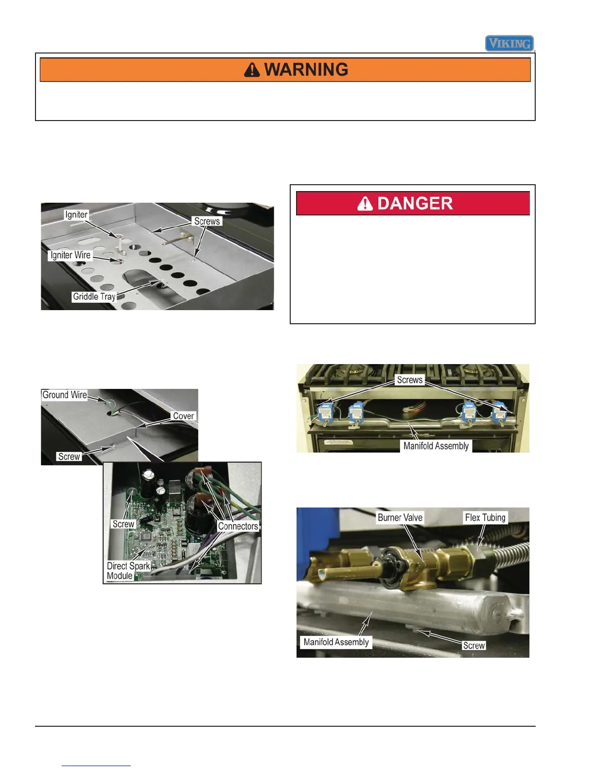
Direct Spark Module Removal
(VDSC536-4G, VDSC548-6G, & VDSC548-4GQ)
Condition Requirements:
Griddle Burner Removed
1. Remove six screws and griddle tray from range.
2. Disconnect igniter wire from griddle igniter.
3. Remove three screws, ground wire and cover from
range.
4. Mark and disconnect four connectors from direct
spark module.
5. Remove four screws and direct spark module from
range.
4. Reverse procedure for installation.
Burner Valve Removal
Condition Requirements:
Control Panel Assembly Removed
Gas Shut Off
Gas leak hazard. To avoid risk of personal injury
or death, leak testing of the appliance must
be conducted according to the manufacturer’s
instructions. Before placing appliance in operation,
always check for gas leaks with soapy water solution.
DO NOT USE AN OPEN FLAME TO CHECK FOR
GAS LEAKS.
1. Remove two screws that secure manifold assembly
to range.
2. Pull to remove module from burner valve.
3. Remove fl ex tubing from burner valve.
4. Remove screw and burner valve from manifold
assembly.
5. Reverse procedure for installation.
6. Perform gas leak test.
 Loading...